


تُعدّ عملية تشغيل مجموعة المولدات عمليةً مُنظّمةً للتحقق من أداء المولد المُركّب حديثًا وفقًا للمواصفات، بدءًا من اختبار القبول في المصنع وحتى التسليم النهائي. وتشمل ثماني مراحل: اختبار القبول في المصنع، وفحص التسليم، وفحوصات ما قبل التشغيل، والتشغيل الأولي، واختبار الحماية، واختبار بنك الأحمال، ودمج نظام التحويل التلقائي، وتسليم الوثائق. قد يؤدي إغفال أي مرحلة إلى إلغاء الضمانات، وفشل عمليات الفحص، وترك الأنظمة الحيوية دون حماية.
عندما استلم فيكتور كوالسكي مولد ديزل بقدرة 500 كيلوواط لمصنع بولندي في أوائل عام 2024، افترض أن الوحدة جاهزة للتشغيل. وقد سلمها المصنّع في الموعد المحدد. وقام مقاول التركيب بتوصيل خطوط الوقود والعادم والكهرباء وفقًا لـ دليل تركيب مجموعة المولدات الكاملةكل شيء بدا صحيحاً.
لكن فيكتور لم يكمل إجراءات التشغيل الرسمية. وبعد ثمانية أشهر، تعطل المولد الكهربائي أثناء انقطاع التيار الكهربائي. ورفضت الشركة المصنعة طلب الضمان.
كان تقرير التشغيل غير مكتمل. وقد تم تمويل الإصلاح الذي بلغت تكلفته 28,000 ألف دولار مباشرة من ميزانية الصيانة الخاصة به.
يُقدّم هذا الدليل إجراءات تشغيل مجموعة المولدات الكهربائية كاملةً، وهي الإجراءات التي تمنى فيكتور لو أنه اتبعها. ستتعرف على الخطوات الدقيقة لكل مرحلة، والوثائق التي تحمي ضمانك، والأخطاء الشائعة التي تُحوّل عملية التسليم البسيطة إلى نزاع مُكلف.
الوجبات السريعة الرئيسية
- تتبع عملية التشغيل دورة حياة من ثماني مراحل تبدأ من المصنع وحتى التسليم، وعادةً ما تبدأ تغطية الضمان عند التشغيل، وليس عند التسليم.
- يجب أن يتبع اختبار بنك الأحمال تسلسل خطوات متدرج بنسبة 25% / 50% / 75% / 100% وفقًا للمعيار ISO 8528 للتحقق من الأداء ومنع التراكم الرطب
- تتطلب أنظمة المستوى الأول من معيار NFPA 110 اختبارات قبول موثقة، وإعلانًا عن بُعد، ونقلًا خلال 10 ثوانٍ.
- يُعد عدم اكتمال وثائق التشغيل السبب الرئيسي لرفض مطالبات الضمان في السنة الأولى من التشغيل
- يقلل اختبار القبول في المصنع (FAT) من وقت التشغيل الميداني عن طريق التحقق من قدرة التحميل قبل مغادرة الوحدة للمصنع
ما هي عملية تشغيل مجموعة المولدات ولماذا هي مهمة؟

التشغيل التجريبي هو العملية الرسمية التي تحوّل المولد من مجرد معدات إلى نظام طاقة موثوق. وهو يربط بين اكتمال التركيب وجاهزية التشغيل. وبدونه، حتى مجموعة المولدات المركبة بشكل صحيح تنطوي على مخاطر خفية.
يتجاهله العديد من المشترين. وهذا خطأ مكلف.
اختبار FAT مقابل اختبار SAT مقابل التشغيل
تتداخل ثلاثة مصطلحات في كثير من الأحيان، لكنها تخدم أغراضًا مختلفة. يُجرى اختبار القبول في المصنع (FAT) لدى الشركة المصنعة قبل الشحن، حيث يتحقق من مطابقة الوحدة لمواصفات الشراء في ظل ظروف مُحكمة.
يُجرى اختبار قبول الموقع (SAT) بعد التركيب في موقع المشروع، للتأكد من أن النقل والمناولة والتركيب لم تؤثر سلبًا على الأداء. تشمل عملية التشغيل كلاً من اختبار قبول المصنع (FAT) واختبار قبول الموقع (SAT)، بالإضافة إلى اختبارات الحماية، والتحقق من صحة بنك الأحمال، ودمج نظام التحويل التلقائي (ATS)، وتسليم الوثائق.
لماذا يحدد التشغيل نطاق تغطية الضمان؟
بالنسبة لكبرى الشركات المصنعة، مثل كمنز، وكاتربيلر، وكوهلر، وإم تي يو، يبدأ سريان الضمان عند بدء التشغيل، وليس عند التسليم. هذه تفصيلة يغفل عنها العديد من مديري المشاريع. قد يؤدي عدم بدء تشغيل الوحدة بشكل صحيح، أو عدم وجود وثائق موقعة، إلى إلغاء تغطية الضمان بالكامل. يُعد تقرير بدء التشغيل الدليل القانوني على أن الوحدة قد تم اختبارها وفقًا للمواصفات عند التسليم.
المعايير التي تحكم عملية التشغيل
تحدد عدة معايير ما يجب أن تتضمنه عملية التشغيل. نفبا شنومكس تُشرف على أنظمة الطاقة الاحتياطية والطارئة في الولايات المتحدة. وتُحدد المواصفة القياسية الدولية ISO 8528-5 والمواصفة القياسية الدولية ISO 8528-6 فئات الأداء وطرق الاختبار لمجموعات مولدات المحركات الترددية.
تغطي المادة 445 والمادة 700 من قانون الكهرباء الوطني (NEC) متطلبات التركيبات الكهربائية وأنظمة الطوارئ. ويتناول معيار IEC 60034 أداء الآلات الكهربائية الدوارة. يجب أن تتوافق إجراءات تشغيل مجموعة المولدات مع المعايير المطبقة في نطاق اختصاصك وتطبيقك.
الجدول الزمني النموذجي حسب حجم النظام
تتفاوت مدة التشغيل تبعاً لتعقيد النظام. فوحدة احتياطية بقدرة 50 كيلوواط لمبنى تجاري صغير تحتاج عادةً من يوم إلى يومين، بينما تحتاج وحدة صناعية بقدرة 500 كيلوواط من ثلاثة إلى خمسة أيام.
قد يستغرق إعداد الأنظمة المتوازية ذات الوحدات المتعددة ومفاتيح التبديل المعقدة أسبوعًا أو أسبوعين. لذا، فإن تخصيص هذا الوقت ضمن جدول مشروعك يمنع إجراء الاختبارات على عجل ونقص الوثائق.
للحصول على تحليل هندسي معمق لمواصفات الخرسانة، ومنتجات عزل الاهتزازات، وحسابات الأحمال حسب فئة الكيلوواط، يُرجى الرجوع إلى دليلنا المخصص حول تصميم أساسات مجموعة المولدات.
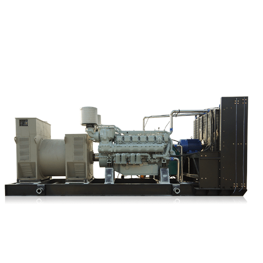
المرحلة الأولى: اختبار القبول في المصنع (FAT)
يُعد اختبار القبول النهائي (FAT) فرصتك الأولى لاكتشاف العيوب قبل مغادرة الوحدة للمصنع. ويُعتبر حل المشكلات في المصنع أقل تكلفة بكثير من حلها بعد وصول الوحدة إلى الموقع.
التفتيش البصري والأبعاد
تحقق من الوحدة ومطابقتها مع أمر الشراء والرسومات المقدمة. تأكد من أبعاد الهيكل، وتكوين القاعدة، وسعة خزان الوقود، ونوع الغلاف، وقدرة المولد. سجل الرقم التسلسلي للمحرك والرقم التسلسلي للمولد. يجب أن تتطابق هذه الأرقام مع الوثائق المرفقة بالوحدة إلى الموقع.
التحقق من بدء التشغيل بدون حمل
شغّل المحرك وتأكد من دورانه بشكل صحيح، ووصوله إلى ضغط الزيت المطلوب، ووصوله إلى السرعة المقدرة، واستقرار الجهد والتردد. بالنسبة لأنظمة 60 هرتز، تكون السرعة المقدرة 1800 دورة في الدقيقة. أما بالنسبة لأنظمة 50 هرتز، فهي 1500 دورة في الدقيقة. يجب أن يستقر الجهد عند القيمة المحددة على جميع الأطوار.
اختبار بنك الأحمال عند السعة المقدرة
قم بتطبيق حمل مقاومة تدريجيًا. التسلسل القياسي هو 25% لمدة 30 دقيقة، ثم 50% لمدة 30 دقيقة، ثم 75% لمدة 30 دقيقة، وأخيرًا 100% لمدة تتراوح بين 60 و120 دقيقة. في كل خطوة، سجّل ناتج الطاقة بالكيلوواط، والقدرة الظاهرية بالكيلوفولت أمبير، ومعامل القدرة، والجهد على جميع الأطوار، والتردد، ودرجة حرارة سائل التبريد، وضغط الزيت، ودرجة حرارة العادم، وضغط الوقود. تُشكّل هذه البيانات خط الأساس للمقارنة خلال اختبار قبول الموقع.
قبول الأحمال المتدرجة وفقًا للمعيار ISO 8528-5
يُحدد معيار ISO 8528-5 فئات الأداء العابر من G1 إلى G4. تتطلب معظم التطبيقات الصناعية الفئة G3، التي تحد من انخفاض الجهد إلى 15-20% وانخفاض التردد إلى 10% أثناء تغيرات الحمل المفاجئة. يجب أن يتم التعافي في حدود ±2% من التردد المقنن و±5% من الجهد المقنن في غضون 3 إلى 5 ثوانٍ.
التحقق من الإنذار والإغلاق
قم بمحاكاة حالات الأعطال وتحقق من استجابة نظام التحكم بشكل صحيح. اختبر إيقاف التشغيل عند انخفاض ضغط الزيت، وإيقاف التشغيل عند ارتفاع درجة حرارة سائل التبريد، وإيقاف التشغيل عند السرعة الزائدة، وقفل التشغيل الزائد، وإنذار انخفاض مستوى الوقود، وإنذار فشل شاحن البطارية، والتوقف الطارئ. يجب أن تُفعّل كل وظيفة الإنذار الصحيح وتسلسل الإيقاف الصحيح.
اختبار مقاومة العزل
قِس مقاومة العزل على ملفات المولد باستخدام مقياس المقاومة العالية (ميغا أوم). يجب أن تتجاوز القراءة 1 ميغا أوم عند 40 درجة مئوية، بعد تصحيحها وفقًا لدرجة الحرارة. سجّل درجة الحرارة المحيطة والرطوبة وقت الاختبار، حيث يؤثر كلاهما على القراءة.
| بند من قائمة التحقق من الدهون | معايير النجاح | توثيق |
|---|---|---|
| الفحص البصري | لا توجد عيوب، مطابق لأمر الشراء | ورقة فحص مع صور |
| بدء التشغيل بدون حمل | يصل إلى السرعة المقدرة، والجهد مستقر | سجل بدء التشغيل بالمعلمات |
| اختبار بنك التحميل | تم إكمال 25/50/75/100% من الخطوات | ورقة بيانات اختبار التحميل |
| قبول تغيير الحمل | ضمن حدود فئة ISO 8528-5 | رسم بياني للاستجابة العابرة |
| التحقق من الإنذار | جميع الوظائف تستجيب بشكل صحيح | قائمة فحص اختبار الإنذار |
| مقاومة العزل | أكبر من أو يساوي 1 ميجا أوم | تقرير اختبار ميجر |
المرحلة الثانية: التسليم وإعداد الموقع

إن ما يحدث بين المصنع والتشغيل الأول قد يحدد نجاح أو فشل عملية التشغيل. يُعدّ التلف أثناء النقل، وفقدان الملحقات، وتلوث السوائل من المشاكل الشائعة التي يمكن اكتشافها مبكراً من خلال فحص دقيق عند الاستلام.
توثيق أضرار النقل
صوّر الوحدة من جميع الزوايا وهي لا تزال على مقطورة النقل. ابحث عن أي انبعاجات أو خدوش أو انحناءات في زعانف المبرد أو تلف في صناديق التوصيل أو تشققات في لوحات التحكم. في حال وجود أي تلف، وثّقه فورًا وأبلغ شركة النقل والشركة المصنّعة قبل تفريغ الوحدة. فبدون صور قبل التفريغ، يصعب إثبات التلف الناتج عن النقل.
التحقق من لوحة الاسم والرقم التسلسلي
تأكد من تطابق بيانات لوحة البيانات مع أمر الشراء. تحقق من قدرة المحرك (كيلوواط)، والجهد، والطور، والتردد، وتصنيف القدرة في وضع الاستعداد مقابل وضع التشغيل الأساسي. سجل الرقم التسلسلي للمحرك والرقم التسلسلي للمولد. قارن هذه البيانات بتقرير اختبار القبول في المصنع (FAT) للتأكد من وصول نفس الوحدة التي اجتازت اختبارات المصنع إلى الموقع.
جرد الملحقات
تأكد من وجود جميع الملحقات المذكورة في طلب الشراء. من بين العناصر الشائعة التي قد تُفقد أثناء الشحن: البطاريات، وشواحن البطاريات، وسخانات مياه التبريد، وأجهزة الإنذار عن بُعد، وموصلات العادم المرنة، ومجموعات قطع الغيار. يؤدي عدم اكتمال قائمة الملحقات إلى تأخير التشغيل حتى وصول البدائل.
تأكيد مستوى السائل
تحقق من مستوى سائل التبريد، وزيت المحرك، والوقود. تأكد من إزالة سدادات الشحن من مخرج العادم، ومدخل الهواء، وفتحة تهوية علبة المرافق. تحمي هذه السدادات المؤقتة المحرك أثناء النقل، ولكن يجب إزالتها قبل التشغيل الأول. تشغيل المحرك مع وجود سدادة الشحن يُسبب تلفًا فوريًا وشديدًا.
المرحلة الثالثة: فحوصات ما قبل التشغيل
لا تُشغّل المحرك حتى تُكمل جميع بنود قائمة فحص ما قبل التشغيل. قد يؤدي إغفال أي بند إلى إلغاء الضمان. بدء التشغيل مع وجود مشكلة لم تُحل يُسبب تلفًا، وقد لا يظهر هذا التلف إلا بعد أشهر.
التحقق الميكانيكي
افحص نظام العادم للتأكد من تركيب الوصلات المرنة بشكل صحيح عند مشعب العادم. تأكد من استخدام وصلات ذات نصف قطر طويل، وأن كاتم الصوت وغطاء المطر مثبتان في مكانهما الصحيح. تحقق من عدم وجود عوائق أمام مدخل الهواء، وأن فتحات التهوية تعمل بحرية.
تأكد من اختبار ضغط أنابيب الوقود، وفحصها للتأكد من عدم وجود تسريبات، وتجهيزها للتشغيل. تحقق من مستويات سائل التبريد وسجل تركيز مانع التجمد. تأكد من إزالة جميع كتل الشحن من عوازل الاهتزاز.
التحقق الكهربائي
أعد قياس مقاومة عزل ملفات المولد الكهربائي وقارن القراءة بنتيجة اختبار القبول النهائي. يشير الانخفاض الكبير في المقاومة إلى تسرب الرطوبة أو تلف أثناء النقل. تأكد من توصيل جميع كابلات الطاقة، وربطها بعزم الدوران المحدد، ووضع العلامات عليها وفقًا لمعايير التوصيل الكهربائي لمجموعة المولد.
تأكد من دوران الطور باستخدام مقياس الدوران. قد يؤدي الدوران العكسي إلى تلف أحمال المحرك عند توصيل المولد لأول مرة. اختبر استمرارية التأريض للتأكد من تأريض هيكل المولد والخط المحايد بشكل صحيح.
للحصول على شرح مفصل حول الامتثال للمادة 445 و700 من قانون الكهرباء الوطني، وتحديد حجم نظام التحويل التلقائي، وتصميم نظام قطب التأريض، راجع دليلنا حول توصيلات كهربائية لمجموعة المولد.
تجهيز البطارية ونظام التحكم
تأكد من تركيب البطارية، والقطبية الصحيحة، وحالة الشحن. عادةً ما تُشحن بطاريات كمنز بنسبة شحن 70% تقريبًا، وقد تتطلب شحنًا مسبقًا قبل التشغيل.
تأكد من توصيل شاحن البطارية بمصدر طاقة تيار متردد موثوق به، ومن أنه يُنتج جهد الشحن الصحيح. تحقق من تشغيل سخانات مياه التبريد وسخانات حوض الزيت. يجب أن تصل درجة حرارة كتلة المحرك إلى درجة الحرارة الموصى بها من قِبل الشركة المصنعة، والتي تتراوح عادةً بين 32 و49 درجة مئوية، قبل التشغيل الأول.
| فئة ما قبل التشغيل | فحوصات المفاتيح |
|---|---|
| نظام العادم | موصل مرن، دعامة، غطاء واقٍ من المطر، ضغط خلفي |
| مدخل الهواء | خالية من العوائق، فتحات التهوية تعمل بكفاءة، تم تركيب فلتر |
| نظام الوقود | تم اختباره تحت الضغط، خالٍ من التسريبات، مُجهز، مُفرغ من الهواء |
| مبرد | مستوى سائل التبريد، تركيز مانع التجمد، مستوى DCA |
| كهرباء | عزم دوران الكابل، دوران الطور، التأريض، مقاومة العزل |
| بطاريات السيارات | حالة الشحن، القطبية، خرج الشاحن |
| طرق المكافحة | طاقة وحدة التحكم الإلكترونية، جاهزية التشحيم المسبق، لا توجد أعطال نشطة |
المرحلة الرابعة: بدء التشغيل الأولي والتشغيل بدون تحميل

تُعدّ عملية التشغيل الأولى اللحظة الأكثر حساسية في عملية التجهيز. لذا، خذ وقتك. قم بتشغيلها يدويًا من لوحة تحكم المولد. لا تقم بتوصيل الحمل حتى يتم التحقق من جميع المعايير.
متطلبات دورة ما قبل التشحيم
شغّل مضخة التزييت المسبق لمدة لا تقل عن 60 ثانية قبل بدء تشغيل المحرك. تأكد من أن ضغط الزيت يصل إلى 30 كيلوباسكال على الأقل، أو 4.4 رطل لكل بوصة مربعة، ويبقى ثابتًا. بدء التشغيل بدون تزييت كافٍ يُسبب تلفًا في المحامل قد لا تظهر أعراضه إلا بعد أشهر، ولكنه يُقصر عمر المحرك بشكل ملحوظ.
إجراءات التشغيل الأولى
شغّل المحرك محليًا في الوضع اليدوي. راقب ما يلي: يجب أن يرتفع ضغط الزيت خلال ثوانٍ، ويجب أن يصل المحرك إلى سرعته المقدرة بسلاسة، ويجب أن يستقر جهد المولد عند القيمة المحددة على جميع الأطوار، ويجب أن يبقى التردد ثابتًا عند 60.0 أو 50.0 هرتز دون أي انحراف. تفقد الوحدة بحثًا عن أي تسريبات للسوائل، أو أصوات غير طبيعية، أو اهتزازات مفرطة، أو مشاكل في نظام العادم.
مدة التشغيل بدون حمل
اترك الوحدة تعمل بدون حمل لمدة تتراوح بين 10 و15 دقيقة. راقب جميع المعايير على لوحة التحكم. أوقف تشغيلها بشكل طبيعي وقم بإجراء فحص ما بعد التشغيل. تحقق مرة أخرى من وجود أي تسريبات، وتأكد من عدم ظهور أي رموز أعطال في وحدة التحكم الإلكترونية، وتأكد من عودة نظام التحكم إلى وضع الاستعداد بشكل صحيح.
المرحلة الخامسة: اختبارات الحماية والتحكم
قم بمحاكاة ظروف الأعطال وتحقق من استجابة نظام التحكم بشكل صحيح في اللوحة المحلية، وجهاز الإنذار عن بعد، ونظام إدارة المباني إذا كان متكاملاً.
التحقق من إيقاف الطوارئ
اختبر زر إيقاف الطوارئ المحلي، وزر إيقاف الطوارئ عن بُعد، وأي عمليات إيقاف يتم تفعيلها بواسطة إنذار الحريق. يجب أن يؤدي كل منها إلى إيقاف المحرك فورًا وإغلاقه حتى إعادة ضبطه يدويًا.
محاكاة الإغلاق الحرج
قم بمحاكاة أو التحقق من حالات الإيقاف التالية: انخفاض ضغط الزيت، ارتفاع درجة حرارة سائل التبريد، زيادة السرعة، إيقاف التشغيل بعد ثلاث دورات تشغيل، إنذار انخفاض مستوى الوقود، عطل في البطارية أو الشاحن، وعطل في نظام التحويل التلقائي. يجب أن تُفعّل كل وظيفة رمز الإنذار الصحيح وتسلسل الإيقاف الصحيح.
تكامل نظام الإنذار عن بعد ونظام إدارة المباني
بالنسبة لأنظمة NFPA 110 المستوى 1، يلزم وجود جهاز إنذار عن بُعد. تأكد من أن جميع حالات الإنذار تُعلن بشكل صحيح في الموقع البعيد. إذا كان المولد مُدمجًا مع نظام إدارة المباني (BMS)، فتأكد من أن الإنذارات وإشارات الحالة تُرسل بشكل صحيح عبر Modbus أو BACnet أو البروتوكول المُحدد.
المرحلة السادسة: اختبار بنك الأحمال والتحميل التدريجي
يُعد اختبار بنك الأحمال أساسياً في أي إجراء لتشغيل مولدات الديزل. فهو يثبت قدرة المولد على تحمل الحمل المقنن، ويؤكد استقراره الحراري.
يؤكد ذلك الأداء العابر. كما أن اتباع إجراءات اختبار بنك أحمال المولد الصحيحة يمنع تراكم الرطوبة قبل حدوثه.
إعداد بنك الأحمال والسلامة
قم بتوصيل بنك الأحمال المقاوم أو التفاعلي وفقًا لتعليمات الشركة المصنعة. تأكد من أن كابلات بنك الأحمال ذات حجم مناسب، وموصولة بإحكام، ومثبتة جيدًا. تحقق من أن مصادر الطاقة الإضافية لمروحة تبريد بنك الأحمال وأجهزة التحكم الخاصة به تعمل. حدد محيطًا آمنًا واضحًا، وخصص مشغلًا للتحكم في بنك الأحمال.
تسلسل التحميل التدريجي
قم بتطبيق الحمل تدريجياً. تسلسل التشغيل القياسي هو:
| خطوة التحميل | المدة | المعلمات المطلوب تسجيلها | الهدف |
|---|---|---|---|
| 25% | 30 دقائق | كيلوواط، كيلو فولت أمبير، الجهد، التردد، ضغط الزيت، درجة حرارة سائل التبريد | الإحماء والأساسيات |
| 50% | 30 دقائق | كما سبق، بالإضافة إلى درجة حرارة العادم | فحص استقرار المدى المتوسط |
| 75% | 30 دقائق | كما سبق، بالإضافة إلى ضغط الوقود | التحقق الحراري الحرج |
| 100% | دقيقة 60-120 | يتم ضبط المعلمات بالكامل كل 15 دقيقة | سعة كاملة وامتصاص حراري |
| 110% | 10 دقائق (إذا تم تحديد ذلك) | مجموعة المعلمات الكاملة | القدرة الزائد |
سجل البيانات كل 5 إلى 15 دقيقة في كل خطوة. راقب وجود أي إنذارات متعلقة بوحدة التحكم الإلكترونية، أو ارتفاع درجة الحرارة، أو أصوات غير طبيعية.
التحقق من الأداء العابر وفقًا للمعيار ISO 8528-5
عند تطبيق كل خطوة من خطوات الحمل، قِس انخفاض الجهد، وانخفاض التردد، وزمن الاستعادة. بالنسبة لأجهزة الفئة G3، يجب ألا يتجاوز انخفاض الجهد 15 إلى 20%، ويجب ألا يتجاوز انخفاض التردد 10%. يجب أن تتم الاستعادة إلى حالة الاستقرار في غضون 3 إلى 5 ثوانٍ. يُؤكد اختبار رفض الحمل، بإزالة الحمل بنسبة 100% فجأة، أن تجاوز الجهد يبقى في حدود 20%، وتجاوز التردد في حدود 12%.
منع تراكم الرطوبة أثناء التشغيل الأولي
التراكم الرطب هو تراكم الوقود غير المحترق ورواسب الكربون الناتجة عن تشغيل المحرك بحمل خفيف لفترات طويلة. أثناء التشغيل التجريبي، يضمن تشغيل المحرك بحمل مُنظّم من 25% إلى 100% وصوله إلى درجة حرارة التشغيل الكاملة، مما يؤدي إلى حرق أي رواسب قد تكونت أثناء اختبارات المصنع أو النقل. إذا لم تتمكن منشأتك من توفير حمل كافٍ للاختبارات الشهرية، فخطط لاختبارات سنوية للحمل لمنع التراكم الرطب أثناء التشغيل.
عندما قام مركز بيانات في دبي بتشغيل وحدة بقدرة 1000 كيلوواط في عام 2023، أجرى المقاول اختبارًا قصيرًا بدون حمل، ثم اختبارًا آخر لمدة 30 دقيقة بحمل 25%. وقد وافق العميل على الوحدة.
بعد ستة أشهر، ظهرت مشكلة تراكم الرواسب في المحرك. أدى تآكل جدران الأسطوانات إلى انخفاض الضغط، وزيادة استهلاك الزيت بنسبة 40%. بلغت تكلفة الإصلاح 45,000 دولار. كان من الممكن إجراء اختبار تحميل تدريجي مناسب أثناء التشغيل التجريبي للوصول إلى درجة حرارة التشغيل الكاملة وإزالة الرواسب قبل أن تتصلب.
إجراءات التبريد
بعد إتمام اختبار التحميل الكامل، خفّض الحمل تدريجيًا إلى ما بين 25% و30%، وثبّته لمدة تتراوح بين 10 و15 دقيقة. هذا يمنع حدوث صدمة حرارية للشاحن التوربيني ومشعب العادم. أوقف تشغيل الوحدة واتركها تبرد قبل إجراء فحص ما بعد الاختبار.
المرحلة السابعة: نظام تتبع المتقدمين وتكامل النظام

يُعد مفتاح التحويل التلقائي (ATS) حلقة الوصل الأساسية بين المولد والحمل المحمي. ويؤكد اختباره في ظروف واقعية أن نظام الطاقة الاحتياطية بأكمله يعمل كما هو مصمم.
التحقق من أسلاك التحكم
تأكد من توصيل جميع أسلاك التحكم بين المولد ومفتاح التحويل التلقائي وجهاز الإنذار عن بُعد بشكل صحيح. تحقق من وصول إشارة بدء التشغيل عن بُعد من مفتاح التحويل التلقائي إلى وحدة تحكم المولد، ومن وصول إشارات الحالة من المولد إلى مفتاح التحويل التلقائي.
اختبار محاكاة انقطاع المرافق
افتح قاطع الدائرة الكهربائية لمحاكاة انقطاع التيار الكهربائي. يجب أن يبدأ المولد تلقائيًا ويصل إلى الجهد والتردد المناسبين خلال الوقت المحدد. بالنسبة لأنظمة NFPA 110 المستوى 1، يجب ألا يتجاوز إجمالي الوقت من انقطاع التيار الكهربائي إلى تحويل الحمل 10 ثوانٍ. يجب أن يقوم نظام التحويل التلقائي (ATS) بتحويل الحمل إلى طاقة الطوارئ بسلاسة دون انخفاضات في الجهد تؤثر على المعدات الحيوية.
شغّل المولد تحت الحمل لفترة متواصلة، عادةً من 15 إلى 30 دقيقة. ثم أعد التيار الكهربائي الرئيسي. يجب أن يقوم نظام التحويل التلقائي (ATS) بإعادة تحويل الحمل إلى التيار الكهربائي العادي وبدء دورة تبريد المولد. تأكد من إيقاف تشغيل المولد تلقائيًا بعد انتهاء فترة التبريد المبرمجة.
المرحلة الثامنة: التوثيق والتدريب والتسليم
لا يكتمل تشغيل المولد بمجرد تشغيله، بل يكتمل بتوقيع حزمة الوثائق، وتدريب المشغلين، وتفعيل الضمان.
الوثائق المطلوبة للتشغيل
يجب أن تتضمن حزمة التسليم ما يلي: تقرير اختبار القبول في المصنع (FAT) المكتمل مع بيانات الاختبار، وتقرير اختبار القبول في الموقع (SAT) المكتمل مع نتائج اختبار بنك الأحمال، وقراءات مقاومة العزل، وقوائم فحص اختبار الإنذار والإيقاف، وسجلات توقيت نقل مفتاح التحويل التلقائي (ATS)، والرسومات التنفيذية، وقائمة فحص تشغيل المولد من الشركة المصنعة مع توقيع الموافقة. بالنسبة لأنظمة NFPA 110 من المستوى 1، يجوز للجهة المختصة طلب دليل على اختبار قبول NFPA 110 وخطاب امتثال NFPA 110.
قائمة مراجعة تدريب المشغلين
يجب أن يشمل تدريب المشغلين إجراءات التشغيل والإيقاف المحلية والبعيدة. راجع مواقع التوقف الطارئ وإجراءات إعادة الضبط. غطِّ مهام الصيانة الروتينية بما في ذلك فحص السوائل وفحص الفلاتر.
درّب المشغلين على تفسير الإنذارات والاستجابة لها. عرّفهم على مكان وكيفية استخدام أدلة التشغيل والصيانة. وثّق التدريب بتوقيعات المتدربين وتاريخه.
تسجيل وتفعيل الضمان
قدّم تقرير التشغيل إلى الشركة المصنّعة لتفعيل تغطية الضمان. يبدأ سريان الضمان عادةً من تاريخ التشغيل. بالنسبة لوحدات Cummins وCaterpillar وKohler، غالبًا ما يتعيّن على ممثل الشركة المصنّعة أو الوكيل المعتمد ضبط عناصر التحكم وتوقيع قائمة التحقق من التشغيل للتحقق من صحة الضمان. بدون هذا التوقيع، قد تُرفض مطالبات الضمان بغض النظر عن سبب العطل.
وضع جدول الصيانة
حدد جدول الصيانة الدورية قبل التسليم. يتطلب معيار NFPA 110 إجراء فحوصات أسبوعية للوقود والزيت وسائل التبريد وحالة البطارية. استخدم نظامنا قائمة فحص صيانة المولد لتتبع هذه المهام.
يُشترط إجراء اختبار تشغيل شهري تحت الحمل لمدة لا تقل عن 30 دقيقة بنسبة 30% أو أكثر من القدرة الاسمية بالكيلوواط. ويُشترط إجراء اختبار سنوي لاختبار الحمل إذا لم يستوفِ الاختبار الشهري باستمرار عتبة 30%. أما بالنسبة لأنظمة المستوى 1، فيُشترط إجراء اختبار كامل للقدرة الاسمية بالكيلوواط لمدة لا تقل عن 4 ساعات كل ثلاث سنوات.
أخطاء شائعة في التشغيل تؤدي إلى إلغاء الضمانات
حتى المقاولون ذوو الخبرة يرتكبون أخطاءً أثناء التشغيل التجريبي. الأخطاء التالية هي أكثر الأسباب شيوعًا لنزاعات الضمان والأعطال المبكرة. تجنب هذه المشكلات لا يقل أهمية عن تجنب أخطاء تركيب مولدات الطاقة الشائعة أثناء مرحلة البناء.
للحصول على تحليل موسع لأخطاء الأساسات، وتسربات العادم، وأعطال التأريض، وغيرها من الأعطال الميدانية مع استراتيجيات الوقاية، راجع دليلنا حول أخطاء شائعة في تركيب مولدات الطاقة.
تخطي تسلسل التحميل التدريجي
إن تشغيل المولد بدون حمل أو بحمل 25% فقط، ثم اعتباره جاهزاً للتشغيل، يُغفل التحقق الحراري الذي يثبت أن نظام التبريد يعمل بكامل طاقته. كما أنه لا يُزيل الرواسب التي تؤدي إلى تراكم الرطوبة.
التوثيق غير الكامل
يؤدي غياب التوقيعات، أو عدم اكتمال بيانات الاختبار، أو عدم توثيق اختبارات الإنذار، إلى ثغرات يستغلها المصنّعون لرفض مطالبات الضمان. يجب أن يكون تقرير التشغيل كاملاً ومقروءاً وموقعاً من جميع الأطراف المعنية.
بدء التشغيل بدون استخدام مواد التشحيم المسبقة
تشغيل محرك بارد دون تشغيل مضخة التزييت المسبق يُسبب احتكاكًا معدنيًا مباشرًا خلال الثواني الأولى من التشغيل. قد لا يتسبب هذا الخطأ البسيط في تلف المحامل إلا بعد أشهر، ولكن عند حدوث ذلك، سيصنفه المصنّع على أنه سوء استخدام.
توقيع ممثل الشركة المصنعة مفقود
يشترط العديد من المصنّعين وجود ممثل معتمد لضبط إعدادات التحكم الرقمي، وتعيين مرحلات الحماية، وتوقيع تقرير التشغيل. تشغيل الوحدة دون هذا التوقيع قد يُبطل الضمان بالكامل، حتى لو تم تركيب المولد بشكل مثالي.
تشغيل أول بدء تشغيل تحت الحمل
يجب أن تتم عملية التشغيل الأولى دائمًا بدون حمل. إن توصيل الحمل قبل أن يصل المحرك إلى درجة حرارة التشغيل المستقرة، وقبل التأكد من ضغط الزيت، وقبل التحقق من المعايير، يُعرّض المولد الكهربائي للتلف ويُبطل الضمان.
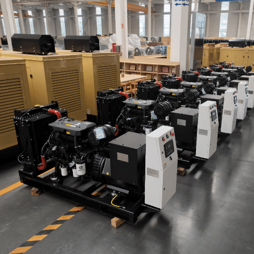
كيف يقلل اختبار المصنع من مخاطر التشغيل الميداني
تصل مجموعات المولدات التي تخضع لاختبارات قبول شاملة في المصنع إلى الموقع مزودة بخطوط أساس أداء مثبتة. وهذا يقلل من وقت ومخاطر التشغيل الميداني بعدة طرق.
يُؤكد اختبار التحميل في المصنع عند سعته المقدرة بنسبة 100% أن المولد والمحرك ونظام التبريد تعمل بشكل صحيح قبل تعريض الوحدة لظروف النقل. تصل لوحات التحكم الرقمية، مثل وحدات التحكم DSE، مُجهزة مسبقًا بالجهد والتردد وإعدادات الحماية الصحيحة. وهذا يُغني عن عملية التجربة والخطأ التي غالبًا ما تُؤخر التشغيل الأولي.
تُسهّل تصاميم قواعد التثبيت القياسية، المتوافقة مع أنظمة عزل الاهتزازات الشائعة، عملية المحاذاة والتسوية أثناء التركيب. وتُسرّع حزم وثائق المصنع الكاملة، التي تشمل مخططات الخط الواحد، ورسومات الأساسات، ومواصفات العادم، وجداول بيانات الاختبار، عملية التحقق قبل التشغيل. كما تُقلّل حزم نظام التحويل التلقائي (ATS) الاختيارية المُهيأة مسبقًا من وقت تشغيل أسلاك التحكم، نظرًا لأن المولد ومفاتيح التبديل تصل مُطابقة ومُختبرة مسبقًا.
عندما تم تشغيل وحدتين بقدرة 750 كيلوواط لكل منهما في مستشفى بجنوب شرق آسيا عام 2024، افترض المقاول أنه بما أن كل وحدة اجتازت اختبارات القبول الفردية، فسيعمل نظام التوازي فورًا. لكن محولات التيار الكهربائي لتوزيع الأحمال وُضعت بشكل خاطئ، ما أدى إلى تنافس الوحدتين بدلًا من توزيع الأحمال.
استغرق الأمر ثلاثة أيام إضافية لإعادة التهيئة لتصحيح خلل التزامن. لو أجرى المصنع اختبار القبول المتكامل المتوازي، لكان قد تم التحقق من تزامن محولات التيار قبل الشحن. كان ذلك سيوفر على العميل الوقت وتكلفة وجود فنيين إضافيين في الموقع.
خاتمة
إنّ اتباع إجراءات التشغيل السليمة لمجموعة المولدات هو الفرق بين مولدٍ موضوعٍ على قاعدةٍ ومولدٍ يحمي عملياتك. إنّ اتباع خطوات تشغيل المولد هذه، بدءًا من اختبار القبول في المصنع وحتى تسليم الوثائق، يضمن التحقق من صحة كل وظيفةٍ حيوية، ويحمي تغطية الضمان، ويضمن الامتثال لمعايير NFPA 110 وISO 8528.
النقاط الرئيسية التي يجب تذكرها واضحة. أكمل كل مرحلة بالتسلسل. وثّق كل اختبار بسجلات موقعة.
اتبع تسلسل اختبار التحميل التدريجي للتحقق من الأداء ومنع تراكم المواد الرطبة. تأكد من موافقة ممثل الشركة المصنعة قبل اعتبار عملية التشغيل مكتملة. درّب المشغلين قبل التسليم، لأن أفضل نظام مُشغّل لا يكون موثوقًا إلا بقدر موثوقية من يُشغّلونه.
بالنسبة لمجموعات المولدات التي تأتي مزودة بمواصفات أساسية تم اختبارها في المصنع وحزم وثائق كاملة، يتم تقليل وقت التشغيل الميداني والحد من المخاطر الميدانية. إذا كنت تخطط لتركيب مولد وتحتاج إلى دعم في إجراءات التشغيل أو ترغب في فهم كامل تكلفة تركيب مجموعة المولداتاتصل بفريقنا الهندسي للحصول على إرشادات مصممة خصيصًا لمتطلبات مشروعك.