
Medium-voltage cable sizing for a generator feeder starts with four inputs: the set’s rated current, its fault current, the earthing method, and the route. On a single generator the fault-current check almost always passes. The screen rating, insulation level, and charging current decide the cable.
That order surprises engineers who learned cable sizing on transformer feeders. The cable that carries 131 A is often selected by a number that never appears in the load calculation.
You have probably sized a cable from a current and an ampacity table. This article shows which habits still work when the source is a generator. We will work a 2.5 MVA example at 11 kV, then set out what to put in the enquiry.
Sizing a set for an 11 kV feeder? Send the load list and the route length, and our engineers will check the generator data against the cable schedule before you order either.
Key Takeaways
- A 2.5 MVA set at 11 kV draws 131 A. A 95 mm² three-core cable is rated 292 A buried, so below about 5 MVA ampacity rarely chooses the cable.
- The same set with X″d of 0.15 pu delivers about 875 A of fault current. A 95 mm² conductor withstands 13.3 kA for one second, so the conductor passes with a factor of 15.
- The cable screen is rated far below the conductor. Earth-fault current and clearing time decide whether it survives, and both follow the generator’s neutral earthing.
- At 11 kV, 300 m of 95 mm² drops 0.16%. The same 2.5 MVA at 480 V needs seven 240 mm² runs and drops 5.8%.
- Charging current is about 1.1 A per km, or 21 kVAR per km. It is negligible on a short lead and material on a multi-kilometre feeder or a small set.
Why a Generator Feeder Is Not a Transformer Feeder
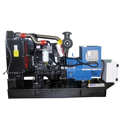
Most mv cable sizing advice starts with the load. Work out the current, pick a size, check volt drop, check fault withstand. That method is correct for a transformer feeder, where the source is a utility bus with a fault level measured in tens of kiloamps.
A generator feeder has a different source. It is a synchronous machine with a subtransient reactance, a fault current that decays, and a hard limit on the leading reactive power it can absorb. Each of those changes which check decides the cable.
The first branch in the method is therefore not the cable. It is the system. Is the generator the only source, or is it paralleled with the utility?
In island operation, the generator sets the fault level and the cable’s charging current is part of the load. In grid-parallel operation, the utility sets the fault level, and the cable must survive a current the generator will never produce. Sizing for the wrong case is the most common expensive error in this subject.
| Check | 2.5 MVA at 11 kV | 2.5 MVA at 480 V |
|---|---|---|
| Load current at 0.8 pf | 131 A | 3,007 A |
| Cable used in this example | 3 × 95 mm² Cu XLPE | 7 × 240 mm² Cu XLPE |
| Copper cross-section | 285 mm² | 1,680 mm² |
| Volt drop over 300 m | 0.16% | 5.8% |
| Initial fault current, X″d 0.15 pu | ≈875 A | ≈20,000 A |
The 480 V column uses seven parallel runs because that is what the current requires. It is not a like-for-like single cable.
Mercia learned the difference on a chrome mine in South Africa in 2019. The cable schedule for a new 2 MVA standby set had been copied from a transformer feeder and specified 100% insulation. The generator neutral was resistance-earthed, which is exactly the case where cable makers expect the 133% level.
The cable was re-quoted, and the commissioning date moved by three weeks. The load current had never been the issue.
Step 1: The Current That Drives Medium Voltage Cable Sizing
Start with the current, because it is the one input everyone agrees on. For a three-phase set, rated current is apparent power divided by the square root of three times line voltage.
At 2.5 MVA and 11 kV, that is 131 A. At 480 V, the same apparent power gives 3,007 A. The voltage does the work, which is why medium voltage exists.
The next table is the 11 kV cable size chart most schedules are missing. It shows what a three-core copper XLPE cable carries at 11 kV, buried in trefoil at 0.8 m depth, with 25 °C ground and soil thermal resistivity of 1.0 K·m/W. The MVA column converts the rating back to apparent power at 11 kV.
| Conductor | Buried rating | MVA at 11 kV | In air, 40 °C |
|---|---|---|---|
| 35 mm² | 171 A | 3.3 | 164 A |
| 50 mm² | 201 A | 3.8 | 195 A |
| 95 mm² | 292 A | 5.6 | 291 A |
| 120 mm² | 330 A | 6.3 | 334 A |
| 185 mm² | 412 A | 7.9 | 426 A |
| 240 mm² | 469 A | 8.9 | 495 A |
| 300 mm² | 521 A | 9.9 | 556 A |
| 400 mm² | 579 A | 11.0 | 629 A |
Ratings are for one installation case. Buried, ducted and air ratings differ by 30% or more once the derating factors are applied, and soil thermal resistivity moves them again. Ask for the basis.
Read the table as a ceiling, not a menu. A single three-core 11 kV cable runs out at about 10 to 11 MVA. Above that you are into parallel runs or single-core cable in trefoil, and equal sharing becomes the design question. Below about 5 MVA, a 95 mm² cable carries roughly half its rating, so ampacity is not what chooses it.
If you are sizing the low voltage side today, our guide to works through that calculation. The medium voltage case replaces its inputs rather than repeating its method.
Step 2: The Fault Current a Generator Can Deliver
Fault current is where medium voltage cable sizing for generators departs from the transformer method. A utility bus can deliver 20 kA or more without flinching. A generator cannot.
Initial symmetrical fault current is set by the subtransient reactance, X″d. Salient-pole machines with damper windings typically sit near 0.20 pu, about five times rated current. Without dampers they can approach 0.30 pu, about three times. Small synchronous machines run from roughly 9% to 17%, giving six to eleven times rated current.
For our 2.5 MVA set, X″d of 0.15 pu gives about 875 A. The current then decays through the transient and synchronous periods, so the value at the relay’s clearing time is lower still.
That matters because the cable check is thermal. The requires S = I√t / k, where k is 143 for copper XLPE and 94 for aluminium XLPE. A 95 mm² copper conductor withstands 13.3 kA for one second. Even a 35 mm² conductor withstands about 5 kA.
Against 875 A, both pass with room to spare. The conductor is not the problem on a single-generator feeder.
The screen is a separate circuit
The metallic screen carries earth-fault current, and its rating is much lower than the conductor’s. One manufacturer’s table for an 11 kV cable gives a 95 mm² conductor a one-second rating of 13.3 kA, but the copper wire screen only 2.6 kA and the copper tape screen 0.7 kA. Treat those figures as indicative and ask the cable maker for the screen’s own kA and time, because construction varies.
This is the check that the load calculation never reaches. A resistance-earthed generator might limit earth-fault current to 200 A or 400 A, and the screen is comfortable. A solidly earthed system can push a multiple of that through the same screen for the same clearing time.
The earthing method also sets the insulation level. As sets out, 100% insulation suits effectively grounded systems that clear a fault within a minute, while 133% suits resistance-grounded systems or clearing beyond an hour. A generator with a neutral grounding resistor sits in the second group by default, which is why the copied transformer schedule fails.
If the generator runs in parallel with the utility, discard this fault level and use the utility’s. The cable, screen and switchgear must be rated for the larger source. decide the clearing time, and has to survive the same fault. Our guide to generator protection relay settings explains how those pickup and time settings are chosen, which fixes the clearing time the screen check depends on.
Step 3: Why Voltage Drop Stops Driving Medium Voltage Cable Sizing
Voltage drop is the check most engineers carry over from low voltage, and at 11 kV it almost stops mattering.
Take the 2.5 MVA example over a 300 m buried route. With 95 mm² copper at 90 °C, resistance is about 0.246 Ω/km and reactance about 0.09 Ω/km. At 0.8 power factor the line-to-line drop is roughly 17 V, or 0.16% of 11 kV.
Now take the same power at 480 V. Seven parallel 240 mm² runs carry about 430 A each. The drop is roughly 28 V, or 5.8% of 480 V. That low voltage design is already outside a typical 3% limit, and it uses 1,680 mm² of copper against 285 mm² at 11 kV.
That is the real economics of medium voltage. It is copper mass, not steady-state voltage drop. A 300 m feeder at 11 kV loses about a sixth of one percent, so the cable is not what limits the run.
Motor starting is a different question, and the answer is still not the cable. For the same 2.5 MVA set, X″d of 0.15 pu is about 7.3 Ω at 11 kV. Three hundred metres of 95 mm² cable is about 0.08 Ω.
The cable is roughly 1% of the source impedance, so upsizing it will not fix a starting dip. A larger set, a soft starter or a drive will.
If the dip is your problem, our article on covers the measurement and the fixes.
Step 4: The Cable Is Also a Load
A medium voltage cable is a capacitor. At 50 Hz its charging current flows whether or not anything is connected at the far end, and the generator has to supply it.
Cable charging current per phase is 2πfCU₀, where C is capacitance per unit length and U₀ is phase voltage. A typical 11 kV XLPE cable has a phase capacitance near 0.56 µF/km, which gives about 1.1 A per km. That is about 21 kVAR per km at 11 kV.
On a 300 m generator lead, the charging current is about 0.3 A and 6 kVAR. Ignore it. On a 5 km feeder to a remote load, it is 5.6 A and 106 kVAR, and the arithmetic starts to matter.
The reason is the generator, not the cable. Charging current is leading reactive power, and a synchronous generator has a limited ability to absorb it. As leading kVAR rises, the automatic voltage regulator reduces field current to hold terminal voltage.
If excitation falls too far, the regulator loses control and voltage rises to whatever the machine’s saturation allows. At low excitation the machine can also slip poles, which damages the rotor.
There is no safe rule of thumb. The is explicit: leading power factor capability depends on the short-circuit ratio, synchronous impedance, pole count, frame size and regulator, and must be read from the reactive capability curve. As a sanity check, the zero-excitation point at no load is roughly kVA rating times short-circuit ratio, and a practical minimum-excitation setting cuts that back.
Mercia’s mine hit this on a 6 km feeder to a pump station. The 800 kW set ran at light load for most of the night, and terminal voltage crept up as the cable’s charging current pushed the machine toward its excitation limit. A shunt reactor at the far end absorbed the charging kVAR. The cable had passed every thermal check.
For a generator feeding a long medium voltage cable, add one line to the datasheet request: leading kVAR capability at the expected real load. If the answer is smaller than the cable’s charging kVAR, you need a different machine or a reactor. Our medium voltage generator guide covers the wider architecture question, including when generating directly at 11 kV makes sense.
Medium Voltage Cable Sizing at 11 kV: Insulation, Screen and Terminations
The cable itself changes at medium voltage, and three details trip up buyers who are used to low voltage.
The first is the voltage designation. An 11 kV cable is usually sold as 6.35/11 kV under BS 6622 or 6/10 kV under IEC 60502-2. Both have a maximum system voltage, Um, of 12 kV.
They are not interchangeable in a tender, so specify Um rather than the marketing voltage. The IEC standard covers extruded cables from 6 kV to 30 kV, and its current edition is .
| Insulation level | When cable makers specify it | 15 kV wall |
|---|---|---|
| 100% | Effectively grounded system, fault cleared within 1 minute | 175 mil |
| 133% | Resistance-grounded system, or clearing over 1 hour | 220 mil |
| 173% | Ungrounded or resonant-grounded system, indefinite fault duration | 280 mil |
Levels and wall thicknesses follow ICEA S-93-639 and AEIC CS8 practice. Confirm the basis with the cable maker.
The second is the minimum size. In North America, NEC Article 311 sets a floor of #2 AWG copper or #1 AWG aluminium. IEC 60502-2 sets no equivalent floor, but catalogues typically start at 25 to 35 mm², and small conductors are avoided because field stress at a small radius is higher. Ask for the manufacturer’s minimum rather than assuming one.
The third is the termination. A medium voltage cable needs a stress cone or geometric stress relief where the screen is cut back, and the work needs a trained joiner. Bend radius is typically 12 times the cable diameter for a shielded cable. The screen must be earthed at every termination and splice, with single-point bonding and a voltage limiter on long runs to avoid circulating currents.
Those details belong in the cable schedule, and they connect to the and the switchgear termination compartment. A cable that passes every electrical calculation can still fail at the gland plate because the termination range does not fit.Our guide to generator switchgear covers the cable compartment, entry and termination arrangements worth confirming before the cable is ordered.
The Cable Schedule: What to Send for a Quotation
Two cable quotations are comparable only if they answer the same questions. Most schedules do not, which is why bids for the same feeder can differ by a third.
Anjali, a contractor in Gujarat, found this on a 3 MVA textile plant tender in 2023. The schedule specified conductor size and route length, and nothing else. The bids came back with different insulation levels, screens and termination kits. Five extra schedule lines closed most of the price gap before award and avoided a variation order later.
Put these in the enquiry:
- System voltage, Um, frequency and the cable standard (IEC 60502-2, BS 6622 or NEC).
- Generator rating, X″d, X/R ratio, SCR and excitation type.
- Island or grid-parallel operation, and the utility fault level if paralleled.
- Neutral earthing method, earth-fault current and clearing time.
- Route length, installation method, soil thermal resistivity, ground temperature, depth and grouping.
- Insulation level, screen type, jacket, armour and termination interface.
Ask each supplier to state the ampacity basis, the screen’s short-circuit rating and the termination range. Those three answers separate a real quotation from a price.
ShanHua builds generator sets from 8 kVA to 4,000 kVA and reviews the electrical data around them. We do not supply cable, so the review is about matching the set to the feeder.
Frequently Asked Questions
How do you size a medium voltage cable for a generator feeder? Start with rated current, then check fault current at the clearing time, the screen’s earth-fault duty and the cable’s charging current. On a single generator the conductor check usually passes easily. The screen and insulation level decide more often than ampacity.
What fault current should I use for an MV cable fed by a generator? Use the initial symmetrical current from the generator’s subtransient reactance, at the actual clearing time. The decay makes that value conservative. If the generator is paralleled with the utility, use the utility fault level, which will be much larger.
Does cable length matter at 11 kV? Not for steady-state voltage drop. A 300 m, 95 mm² feeder drops about 0.16%. Length matters for charging current, about 1.1 A per km, and for earth-fault and bonding design on long runs.
Can a long MV cable cause generator overvoltage? Yes. Charging current is leading reactive power, so the regulator reduces excitation to hold voltage. Beyond the machine’s leading capability it loses control and voltage rises. A shunt reactor or a larger set is the usual fix.
What size cable do I need for a 2 MW generator at 11 kV? At 0.8 power factor the set draws about 131 A. A 95 mm² three-core cable is rated about 292 A buried, so insulation level, screen duty and route set the size, not current. Confirm the installation assumptions first.
Does the cable screen need its own short-circuit rating? Yes. The screen carries earth-fault current, and its one-second rating can be an order of magnitude below the conductor’s. Neutral earthing sets the current, and protection settings set the time.
The Four Checks, in the Right Order
Medium voltage cable sizing for a generator feeder is not a harder version of the low voltage calculation. It is a different calculation with one familiar input.
Current still matters, but below about 5 MVA it rarely chooses the cable. Fault current matters, but on a single generator it passes easily, and the screen is the part to check. Voltage drop stops being a cable problem at 11 kV, which is why medium voltage pays in copper rather than lost volts. And charging current turns the cable into a load the generator must absorb.
Put those four in the right order and the cable schedule becomes short and defensible. Put them in the low voltage order and you will buy conductor you do not need while the screen and insulation level go unchecked.
If you are specifying a set for an 11 kV feeder, send the load list, the route and the earthing method. Our engineers will check the generator data against the cable schedule, so the medium voltage cable sizing is settled before either is ordered.