
Generator protection relay settings aren’t a list of numbers copied from the last project. They are a coordinated set of functions, and at medium voltage that set is the output of a study. The study exists because of one awkward fact: the fault current falls while the relay is deciding.
You’ve probably got a relay datasheet or a quote in front of you, and both confirm that protection is included. Neither tells you what the elements will be set to, who calculates them, or what happens when a setting is carried across from a similar machine. That gap is where most MV generator protection problems begin.
This article covers the four outputs a setting study produces, why 51V exists and how its two numbers are chosen, the functions an LV standby set rarely needs, and the data pack you have to supply before any of it can be calculated. If you’ve already got that pack, our engineers can tell you what’s missing before the study is commissioned.
Key Takeaways
- 51V exists because a generator’s fault current decrements. A plain 51 set above rated current can watch a real fault fade below pickup and never trip.
- Typical starting points are 175% of rated current for voltage-restrained 51V with zero restraint at 100% voltage, or 50% for voltage-controlled with control at 80%.
- Reverse power (32), sync check (25), frequency (81), bus differential (87B) and breaker failure (50BF) are the functions an LV standby set rarely has, and you can’t copy their settings across prime movers or schemes.
- A 200/1, 5P5 current transformer reaches its accuracy limit at 1,000 A, so a 12 times fault on a 105 A machine saturates it before the relay sees the current.
- The study has a deliverable: a function list, a setting sheet, coordination plots and an as-left test record. Ask who signs it, because that name is the hand-over.
Generator Protection Relay Settings: What the Study Produces
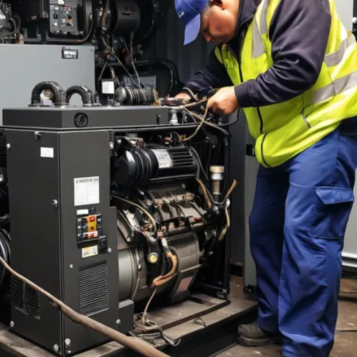
A protection relay setting calculation produces four things, and only one of them is a number. The relay decides and the breaker interrupts, a split that generator switchgear is built around. The setting is what tells the relay how to decide.
| Output | What it contains | Who uses it |
|---|---|---|
| Function list | Which ANSI functions the machine needs, and which are disabled | Design review and procurement |
| Setting sheet | Every element, its pickup, curve and time delay | The person programming the relay |
| Coordination plots | Time-current curves for the generator, the feeder and the utility | The utility and the protection engineer |
| As-left record | The settings actually in the relay after testing, with the firmware version | Commissioning, and anyone investigating a trip later |
Each output depends on the machine and the system it connects to. A 2,000 kVA set at 11 kV and a 20,000 kVA set at the same voltage don’t share settings, even if they come from the same factory and sit in the same building. That’s the difference between generator protection settings and a product datasheet.
The setting is the last line of the study, not the first
The sequence runs from the fault study to the function list, then to the current and voltage transformers, then to the settings, then to coordination, then to the test. A number chosen before that chain is a guess with a decimal point.
The medium voltage generator guide covers why the set sits on 11 kV in the first place. Here the question is narrower: once it’s there, how does anyone decide what the relay should do?
51V: The Setting That Exists Because the Current Falls
A generator’s fault current decays. It’s high at the instant of the fault and much lower by the time a time-delay element has counted down. A feeder assumes the opposite, and you’ll find that assumption in most overcurrent settings.
A current that shrinks under the relay
A plain 51 element set at 150% of rated current assumes the current won’t drop that value below before the delay expires. On a generator terminal fault, the current can fall below the pickup before the delay runs out. The element then resets, and the fault is left to whatever protection sits upstream.
51V answers that. It’s an overcurrent element with a second input from the voltage transformers, so its pickup follows the voltage as well as the current.
Voltage-restrained and voltage-controlled are different settings
Both use voltage, and they don’t behave the same way. A voltage-restrained element reduces its pickup continuously as the voltage falls. A voltage-controlled element keeps a fixed pickup and uses voltage to block or permit the element.
Basler’s generator protection application guide gives the clearest demonstration of restraint. Set the pickup at 175% of rated current at rated voltage, and at 25% voltage it picks up at 1.75 × 0.25 = 0.44 times rated current. That arithmetic is Basler’s, not ours. It shows exactly what the function is for.
| Voltage-restrained (51VR) | Voltage-controlled (51VC) | |
|---|---|---|
| Pickup | Falls as voltage falls | Fixed, typically lower |
| Voltage element | Scales the pickup | Blocks or permits the element |
| Typical starting point | 175% of rated current, zero restraint at 100% voltage | 50% of rated current, control voltage 80% |
| Trade-off | Pickup moves during the fault, so coordination needs care | Easier to coordinate, but the pickup stays where it was set |
The two numbers that decide it
A 51V relay setting has two halves: the current pickup and the voltage pickup. IEEE C37.102 has recommended a current pickup near 150% of full-load current, with the voltage element at or below 0.75 pu. Basler’s typical table starts at 175% with zero restraint at 100% voltage.
The two aren’t far apart, and both are starting points, not rules. A machine that decrements quickly needs a lower voltage threshold than one that holds current longer. Only the fault study shows which case applies, which is why generator relay coordination treats the voltage element and the current pickup as one setting.
Oskar Lindqvist ran a 6 MW gas engine at a district heating plant outside Gothenburg. In 2021 a contractor set the overcurrent element at 120% of rated, carried across from a feeder schedule at another site. It passed secondary injection at rated voltage, so the test sheet was clean.
The first real line fault lasted about 300 ms. The generator current was already under 120% of rated when the time delay expired, so the element reset. The plant’s main breaker cleared the fault 1.4 seconds later, after the stator had absorbed the energy.
The repair took eleven weeks. The fix was a 51V element, not a larger breaker.
Five Generator Protection ANSI Functions an LV Set Rarely Needs
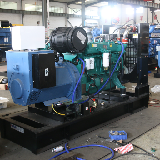
These five exist because the set works alongside other sources and breakers, not because it runs at medium voltage. A standby set in a basement rarely has them. A prime-power or paralleled MV set almost always does.
| Function | ANSI | What it prevents | Typical starting point |
|---|---|---|---|
| Reverse power | 32 | The set motoring and driving the prime mover | 1% of rated, 15 s for a turbine; 10%, 5 s for a reciprocating engine |
| Sync check | 25 | Closing the breaker out of phase | 6 RPM slip, 10 degrees, 2.5% voltage |
| Frequency | 81 | Islanded over- or under-frequency operation | 57/62 Hz at 0.5 s; island 59/61 Hz at 0.1 s |
| Bus differential | 87B | A fault on the busbar the set feeds | Set by the study, from CT ratio and slope |
| Breaker failure | 50BF | A breaker that fails to open on command | Set by the study, from the breaker’s clearing time |
32 depends on the prime mover
Reverse power is the clearest example of a setting that can’t be copied. A steam or gas turbine can be driven backwards by the generator with very little power, so the element is set low, around 1% of rated, with 15 seconds to confirm. A reciprocating engine has more torque pulsation and needs a higher setting, around 10%, with a 5-second delay.
Put the turbine value on a diesel or gas engine and you’ll get nuisance trips. Put the engine value on a turbine and the element won’t operate before the gearbox is damaged. Same function, same relay, different machine.
25 and 81 decide whether you can parallel at all
Sync check is the permission to close. The typical starting point is a maximum slip of 6 RPM, a phase-angle window of 10 degrees and a voltage window of 2.5%. A wider window closes faster and stresses the breaker and the winding. A narrower one can refuse a legitimate close while the governor hunts.
Frequency protection has two jobs, and they don’t share a setting. Against a large grid, 57 and 62 Hz at 0.5 s protect the machine from a system event. Running islanded, the window tightens to 59 and 61 Hz at 0.1 s, because a small island has little inertia to carry it through a load step.
Idris Balogun commissioned a 1.5 MW landfill-gas set near Lagos in 2022. The reverse-power element arrived set at 1% of rated with a 15 second delay, copied from a turbine package at the same site. Gas flow varied with the flare, and the engine motored briefly several times a week.
The relay tripped the set five times in the first month, and each trip cost a restart and a flaring event. The correct setting for a reciprocating engine was 10% with a 5-second delay. The trips stopped. Nothing changed except two numbers.
CT and VT: The Setting Only Works If the Measurement Does
Generator protection relay settings are instructions to compare a measured quantity with a threshold. If the measurement is wrong at the current that matters, you’ve set the wrong number even when the arithmetic is right.
Protection class, not metering class
A metering transformer is built to be accurate at rated current. A protection transformer is built to stay reasonably accurate far above it. IEC 61869-2 defines the protection classes 5P and 10P. The first digit is the composite error at the accuracy limit factor, and the second is that factor.
Two lines on the datasheet decide whether the transformer can serve the setting: the accuracy limit factor and the burden. A 5P10 core holds 5% composite error up to ten times rated primary current, provided the connected burden stays within its rating. Add a longer secondary run or a second relay on the same core and the effective factor falls.
The arithmetic that catches people
A 2,000 kVA set at 11 kV carries about 105 A of rated current, by our arithmetic. A 51VR pickup at 175% is 184 A, and a 51VC pickup at 50% is 52.5 A. On a 200/1 transformer those are 0.92 A and 0.26 A on the secondary.
Now the fault. A 200/1, 5P5 transformer has an accuracy limit of 5 × 200 = 1,000 A. A fault at twelve times rated current is 1,260 A. The core saturates before the relay sees the full current, so the element that was meant to ride the decrement is fed a distorted, reduced version of it.
A 5P10 core on the same ratio reaches 2,000 A, and a 5P20 reaches 4,000 A. The ratio didn’t change. The class did.
| Class on a 200/1 core | Accuracy limit | Covers a 1,260 A fault? |
|---|---|---|
| 5P5 | 1,000 A | No |
| 5P10 | 2,000 A | Yes, with margin |
| 5P20 | 4,000 A | Yes, for higher fault levels |
Ratio, and the fuse that turns a setting into a trip
At 11 kV the rated current is small, so a transformer sized for the cable can be far too large for the machine. A 600/1 core leaves rated current at 17.5% of its range. If the relay’s lowest dependable setting is 0.05 A secondary, the smallest primary current it can resolve is 30 A, or 29% of rated. A 51VC pickup at 50% still fits, but a lower setting doesn’t.
Voltage transformers carry their own requirements: ratio, burden and a fuse-failure scheme. A blown fuse removes the voltage input, and without function 60 the relay reads the loss as a sustained undervoltage. A controlled element is then enabled by the low voltage, and a restrained element drops to its lowest pickup. Either one can turn into a trip on load current, which is why fuse-failure logic is part of the setting, not an accessory.
What to Hand the Protection Engineer, and Who Signs
A study can’t start without data, and most of the delay in a protection package is the wait for it. The list isn’t long, and the buyer or the manufacturer already holds every item.
- Single-line diagram showing the generator, breaker, transformer and utility interface
- Subtransient reactance and X/R ratio for each machine
- Decrement curve and damage curve from the manufacturer
- CT ratios, classes, accuracy limit factors and burdens; VT ratios and burdens
- Neutral grounding arrangement and the earth-fault current limit
- Utility relay curves, fault levels and any coordination requirements
- Operating modes, whether islanded, paralleled or both, and how often each applies
Every item changes at least one setting. The X/R ratio changes the decrement, the neutral grounding arrangement changes the earth-fault element, and the operating modes decide whether 32 and 81 are enabled at all.
If the set reaches the grid through a step-up transformer, the generator step-up transformer guide covers the impedance the coordination plot has to include.
The deliverable, and the signature
The study ends with a package, not a conversation. It holds the function list, the setting sheet, the coordination plots, the as-left test record and the firmware version of each relay.
As-left matters more than as-found. As-found tells you what the relay held when the tester arrived. As-left tells you what it holds when it goes into service, and it’s the only record that answers a question after a trip. Secondary injection is how that record is produced: current and voltage are injected into the relay, and every element is checked against the sheet during protection and control testing.
Someone has to sign it. The candidates are the manufacturer, the switchgear builder, the protection consultant and the commissioning engineer. The contract often names none of them.
The numbers then don’t belong to anyone in particular. A signature isn’t bureaucracy. It’s the only way to know which of four parties owns the setting.
Selin Aydin took over a 3.5 MW plant in Izmir in 2023. The hand-over folder held a printed settings file, no signature and no firmware version. Eighteen months later a reverse-power trip stopped the plant during a grid disturbance, and nobody could show whether the element had been set to the sheet or typed on site.
The investigation took four weeks and ended without a conclusion. A signed page would have settled it in an hour. If you’re assembling that data pack now, send it to our engineers and we’ll tell you which items are missing before the study starts.
Frequently Asked Questions About Generator Protection Relay Settings
What settings does a generator protection relay need?
The set usually starts with generator differential (87G) and stator earth fault, then adds overcurrent and a 51V element where the fault current decrements. A paralleled set adds 32, 25, 81, 87B and 50BF as the scheme requires. The values come from the study, not from a standard list.
What is a 51V relay setting?
51V is an overcurrent element whose pickup is influenced by voltage. Voltage-restrained versions reduce pickup as voltage falls, and voltage-controlled versions block or permit a fixed pickup below a voltage threshold. Typical starting points are 175% of rated current with zero restraint at 100% voltage, or 50% with control at 80%.
What CT class is used for generator protection?
Protection classes 5P or 10P, with an accuracy limit factor high enough to cover the maximum fault current the relay has to see. On a 200/1 core, 5P5 limits accuracy to 1,000 A and 5P10 to 2,000 A, so the class is chosen from the fault level, not from the current rating alone.
Who sets the generator protection relays?
Whichever party the contract names, and it should name one: the manufacturer, the switchgear builder, a protection consultant or the commissioning engineer. Without a named owner the settings default to whoever is available, and the as-left record often doesn’t get signed.
What is included in a protection setting study?
A function list, a setting sheet, coordination plots and an as-left test record. The inputs are the single-line diagram, machine reactances and X/R, CT and VT data, grounding, utility data and the operating modes.
What is the difference between 51 and 51V?
A plain 51 uses current only and assumes the fault current holds above pickup until the breaker opens. A 51V adds a voltage input so the element can still operate after the current has decremented. On a generator, the plain 51 is the setting most likely to miss a real fault.
Generator Protection Relay Settings End With a Signature
Generator protection relay settings are a study output. The function list, the setting sheet, the coordination plots and the as-left record are the four things to ask for, and a number without them is a number with no owner.
51V is what separates MV generator protection from feeder protection: the current falls while the relay is deciding, so the pickup has to follow the voltage. The MV functions (32, 25, 81, 87B and 50BF) exist because the set works alongside other sources, and their settings depend on the prime mover and the scheme. The current and voltage transformers decide whether any of it can work.
Before the next project, ask two questions. What data does the engineer need, and who signs the result? Our engineers can review the data pack and tell you what is missing, and what it changes.