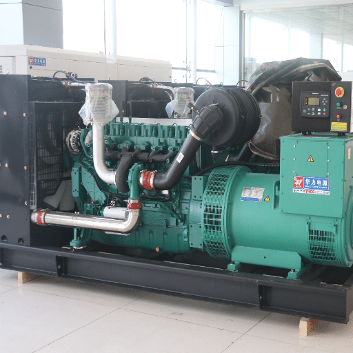

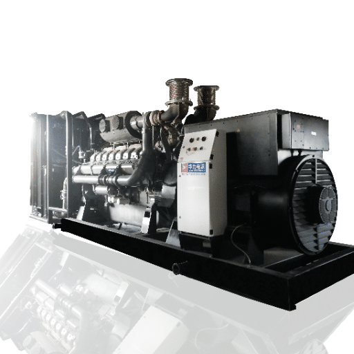
A properly designed generator set foundation prevents equipment failure, protects warranty coverage, and ensures decades of reliable power output. Generator set foundation design involves calculating static and dynamic loads, selecting the correct concrete specifications for your kW class, choosing appropriate vibration isolation, and verifying soil bearing capacity before the first cubic meter of concrete is poured.
What if a 2,000foundationmistakedestroyeda2,000foundationmistakedestroyeda180,000 generator? It happens more often than most project managers expect. Foundation errors are one of the leading causes of generator warranty disputes within the first three years. Manufacturers like Cummins and Caterpillar require documented foundation compliance, and a non-compliant pad can void coverage when you need it most.
You already know that a generator is only as reliable as the support beneath it. In this guide, you will learn how to calculate foundation loads, select concrete pad specifications by kW class, choose the right vibration isolation system, and avoid the mistakes that cost projects tens of thousands in repairs. Whether you are managing a single 100 kW backup unit or a multi-megawatt paralleling installation, the principles here will keep your power solution stable from day one.
For an expanded analysis of foundation errors, exhaust leaks, grounding faults, and other field failures with prevention strategies, see our guide on common generator set installation mistakes.
Key Takeaways
- Generator set foundation design requires load calculations for static weight, dynamic vibration forces, and seismic conditions before concrete selection.
- Concrete pad thickness ranges from 200 mm for small units to 500 mm for 1000-2000 kW systems, with minimum C25/30 concrete for units under 250 kW and C35/45 for units above 1000 kW.
- Vibration isolation selection depends on kW class and building sensitivity: cork pads for small outdoor units, spring isolators for medium commercial installations, and inertia bases for critical facilities or rooftop applications.
- Soil bearing capacity must exceed 150 kPa; soft clay or loose fill requires remediation before pad construction.
- Factory-supplied foundation drawings with pre-calculated load data and anchor bolt templates eliminate field guesswork and reduce structural engineering costs.
What Is Generator Set Foundation Design and Why It Matters

Generator set foundation design is the structural engineering process of creating a support system that safely carries the static weight, dynamic vibration forces, and environmental loads of a generator set throughout its operational life. The foundation is not merely a slab of concrete. It is a load-bearing structure that must resist cracking, settlement, resonance, and anchor bolt pull-out under continuous or intermittent operation.
Foundation failures follow predictable patterns. Settlement occurs when soil bearing capacity is insufficient. Cracking develops when concrete strength is too low or reinforcement is inadequate. Resonance happens when foundation natural frequency aligns with engine operating frequency. Anchor pull-out results from improper embedment depth or misaligned bolt patterns. Each failure mode has one thing in common: it is preventable with proper engineering.
The warranty implications are significant. Cummins requires minimum 21 MPa concrete for all installations and reserves the right to void warranty coverage for non-compliant foundations. NFPA 110 requires generator sets to be installed on “rigid supports,” a requirement that authorities having jurisdiction interpret as properly engineered foundations. Your foundation is the first physical step in the generator set installation process. Errors here cascade through the entire project.
When Marcus, a project contractor in Kenya, installed a 300 kW diesel generator for a manufacturing facility in early 2025, he used a 150 mm thick residential-grade pad poured directly onto clay soil. The concrete was C20/25, the kind used for sidewalks, not industrial equipment. Within eight months, the pad cracked along its centerline, anchor bolts loosened, and the generator shifted 15 mm out of alignment. The repair bill came to $8,000 for re-alignment, re-grouting, and a new reinforced pad. The original “savings” of skipping proper foundation engineering cost four times what doing it right would have.
Foundation Load Calculations: Static, Dynamic, and Seismic
Before selecting concrete grades or pad dimensions, you must quantify the loads the foundation will carry. This analysis has three components: static load from the generator mass, dynamic load from engine vibration, and seismic load for installations in earthquake-prone regions.
Static Load Analysis
Static load is the total dead weight resting on the foundation. It includes the engine, alternator, skid base, enclosure, and fuel. The calculation is straightforward but must be comprehensive.
Formula: W_total = W_engine + W_alternator + W_skid + W_enclosure + W_fuel
For a typical 500 kW diesel generator set, the dry weight of engine and alternator might be 4,500 kg. The skid adds 800 kg. A weatherproof enclosure contributes 1,200 kg. A full fuel tank for 8 hours of runtime at 75% load adds another 1,500 kg. The total static load reaches approximately 8,000 kg. This value determines the minimum pad area required to keep soil bearing pressure within acceptable limits.
Dynamic Load Factors
Diesel engines generate unbalanced forces due to reciprocating motion. These forces transmit through the skid to the foundation and can cause vibration, noise, and structural fatigue if not properly managed. Dynamic load depends on engine speed, unbalanced mass, and crankshaft geometry.
Formula: F_dynamic = m x e x omega^2
In practical terms, project managers do not calculate this from first principles. Generator manufacturers provide dynamic load data in technical datasheets. What matters is that the foundation mass and stiffness must be sufficient to limit vibration amplitude to acceptable levels. A common rule of thumb is that the foundation mass should be 1.5 to 2.5 times the generator mass for units without inertia bases.
Soil Bearing Capacity Requirements
The soil beneath the pad must support the combined static and dynamic loads without excessive settlement. Minimum bearing capacity for most generator applications is 150 kPa, equivalent to 3,000 pounds per square foot. Dense gravel and hard rock provide excellent support. Medium sand and stiff clay are suitable with proper pad sizing. Soft clay and loose fill require remediation.
For generator sets above 500 kW, a geotechnical report is standard practice. If soil capacity is insufficient, options include soil replacement with compacted aggregate, piling to bearing strata, or mat foundations that distribute load over a larger area. Never pour a generator pad without knowing what lies beneath it.
Seismic Load Considerations
Installations in seismic zones must comply with IBC and ASCE 7 requirements. Seismic design considers the generator’s mass, site acceleration parameters, and the ductility of anchor bolt connections. In high-seismic regions such as Japan, California, and Chile, anchor bolts must be designed for tension and shear forces generated during ground motion. Post-installed anchors are generally not permitted for seismic applications; cast-in-place bolts or undercut anchors are required.
For dB level targets by application, enclosure types, and acoustic barrier design, see our article on generator set noise reduction.
Concrete Pad Specifications by kW Class

The most practical way to specify a generator foundation is by kW class. The following table provides concrete pad dimensions, grades, and reinforcement for units from 20 kW to 2000 kW. These specifications assume good soil bearing capacity and level installation sites.
| kW Class | Pad Length (mm) | Pad Width (mm) | Min Thickness (mm) | Concrete Grade | Rebar Grid |
|---|---|---|---|---|---|
| 20-50 kW | 2,000 | 1,000 | 200 | C25/30 | 10mm @ 200mm |
| 50-100 kW | 2,500 | 1,200 | 250 | C25/30 | 12mm @ 200mm |
| 100-250 kW | 3,000 | 1,500 | 300 | C30/37 | 12mm @ 150mm |
| 250-500 kW | 3,500 | 1,800 | 350 | C30/37 | 16mm @ 150mm |
| 500-1000 kW | 4,500 | 2,200 | 400 | C35/45 | 16mm @ 150mm |
| 1000-2000 kW | 5,500 | 2,800 | 500 | C35/45 | 20mm @ 150mm |
Pad Design Rules
These dimensions follow established engineering practice. The pad must extend 150 to 200 mm beyond the generator skid on all sides to provide edge distance for anchor bolts and to distribute load beyond the equipment footprint. For outdoor installations, the top of the pad should sit 100 to 150 mm above finished grade to prevent water pooling around the base. The top surface should slope at 1:100 away from the generator to direct drainage outward. Cable trenches or conduit penetrations should be cast into the pad during forming rather than drilled afterward. In cold climates, pad depth must extend below the frost line, typically adding 300 to 600 mm to the overall excavation depth.
Concrete Mix Requirements
Minimum compressive strength depends on unit size. Units under 250 kW require C25/30 concrete minimum. Units from 250 to 1000 kW need C30/37. Units above 1000 kW require C35/45. In US terminology, these correspond to approximately 4,000 psi, 4,500 psi, and 5,000 psi respectively. Curing time is critical. Concrete reaches approximately 65 to 70% of its 28-day strength after 7 days. Do not place the generator on the pad before 7 days have elapsed. Full 28-day strength should be verified before applying full operational load. During the pour, proper vibration and consolidation prevent voids that weaken the pad and create water ingress paths.
Want to see how foundation costs scale across kW classes? Our breakdown of generator set installation cost by project size gives realistic budget ranges from small backup systems to multi-megawatt industrial installations.
Anchor Bolt Design and Placement
Anchor bolts secure the generator skid to the foundation and must resist horizontal seismic forces, dynamic vibration, and thermal expansion without loosening over time.
Bolt Pattern Specifications
The bolt pattern must match the manufacturer’s drawing exactly. Cummins, Caterpillar, MTU, and Perkins each use different bolt spacing, and field modifications are not acceptable. Typical bolt sizes range from M16 for small units to M36 for large industrial generator sets. Embedment depth should be 12 to 16 times the bolt diameter. Edge distance from the bolt centerline to the pad edge must be at least 100 mm to prevent concrete breakout.
Bolt Installation Methods
Cast-in-place bolts are the preferred method for new construction. They provide the highest pull-out strength and are required for seismic applications. The bolts are set in the formwork using a template that matches the skid mounting holes exactly. Post-installed anchors are used for retrofit applications where the pad already exists. Sleeve anchors are suitable for light loads. Epoxy anchors provide better performance. Undercut anchors offer the highest post-installed capacity and are sometimes accepted for seismic zones.
The most common field error is bolt misalignment. If bolts are off by even 10 mm, the generator skid cannot be seated without field drilling or slotting, which compromises both structural integrity and warranty coverage. Always verify bolt placement against the manufacturer’s template before the concrete pour.
Vibration Isolation Systems: Selection Guide

Vibration isolation prevents engine oscillation from transmitting into the building structure or surrounding soil. The wrong isolation type leads to occupant complaints, equipment fatigue, and structural damage. The right isolation type ensures quiet, stable operation.
Type 1: Cork and Neoprene Pad Isolators
Cork and neoprene pads are the simplest isolation solution. They are placed between the generator skid and the concrete pad. Deflection is low, typically 2 to 5 mm. Isolation efficiency at 1800 RPM is approximately 60 to 70%. These pads are suitable for units under 150 kW installed on rigid soil in industrial or outdoor settings where nearby occupants are not sensitive to vibration. Cost is minimal, and installation requires no special expertise.
Type 2: Spring Isolators
Spring isolators provide 25 to 50 mm of deflection and achieve 85 to 95% isolation efficiency at operating speed. They are the standard choice for units from 150 to 1000 kW, for generators installed inside commercial buildings, and for hospital applications where vibration transmission must be minimized. Spring isolators require a housekeeping pad or raised structural frame to accommodate the deflection gap. Initial cost is moderate, and alignment during installation requires attention.
Type 3: Inertia Bases
An inertia base is a reinforced concrete block mounted on spring isolators. The concrete mass, typically 2,000 to 5,000 kg, lowers the system’s center of gravity and increases inertia, dramatically reducing vibration transmission. Inertia bases achieve 95 to 98% isolation efficiency and are the required solution for units above 1000 kW, for all rooftop installations, and for critical facilities such as data centers and hospitals. Structural engineering is required to design the inertia block and verify that the supporting structure can carry the total weight.
Vibration Isolation Decision Framework
| Application | kW Range | Building Type | Recommended Isolation |
|---|---|---|---|
| Outdoor, rigid soil | <250 | Industrial | Cork/neoprene pads |
| Outdoor, soft soil | 250-1000 | Industrial | Spring isolators |
| Indoor, ground floor | 100-500 | Commercial | Spring isolators |
| Indoor, upper floor | <500 | Any | Inertia base + springs |
| Rooftop | Any | Any | Inertia base + springs |
| Hospital/data center | Any | Critical | Inertia base + springs |
Hospital applications typically require 90% isolation efficiency at operating RPM to meet stringent noise and vibration standards. If your project involves sensitive environments, consult the manufacturer’s vibration data and select isolation accordingly. For more guidance on indoor constraints, see our article on indoor versus outdoor generator set installation.
Special Foundation Designs
Not every installation fits the standard pad-on-grade model. Paralleling systems, indoor installations, and rooftop placements each impose unique foundation requirements.
Paralleling System Foundations
When multiple generator sets operate in parallel, foundation design must accommodate alignment tolerances for switchgear connections, bus duct routing, and exhaust stacking. A common slab simplifies alignment but requires expansion joints between units to prevent thermal stress cracking. Individual pads on a common mat provide more isolation but demand tighter elevation control. Shared inertia bases are sometimes used for identical units in critical facilities.
Indoor Foundation Constraints
Indoor generator rooms must integrate the foundation with building systems. Structural floor loading limits must be verified by a structural engineer, especially for upper-floor installations. Sump pits and drainage channels should be cast into the pad to handle coolant spills or washdown water. Ventilation duct penetrations through the foundation require fire-rated sealing. Vibration transmission to the building structure is a greater concern indoors, which is why spring isolators or inertia bases are typically required.
Rooftop Installations
Rooftop generator installations always require structural load verification by a licensed engineer. The combined weight of the generator, fuel, and inertia base can exceed 15,000 kg for a 1000 kW unit on a concrete inertia base. Wind load anchoring must be calculated for the local design wind speed. Crane access and a hoisting pad must be planned before the building roof is completed. Inertia bases are required for all rooftop installations to isolate vibration from the building frame.
Common Foundation Mistakes and How to Avoid Them
Even experienced contractors make foundation errors. Recognizing the warning signs early prevents expensive remediation.
Insufficient soil bearing capacity produces pad cracking within six months and visible generator shifting. The prevention is simple: obtain a geotechnical report for all installations above 250 kW, and verify soil capacity for smaller units using a handheld penetrometer or local building department records.
Wrong concrete strength causes spalling, surface degradation, and anchor bolt pull-out. Residential-grade concrete at C20/25 or 3000 psi is not suitable for industrial generator sets. Use the kW-class table in this guide and never go below the minimum grade.
Inadequate vibration isolation leads to building vibration, occupant complaints, and in severe cases structural damage to walls and ceilings. Match the isolation type to the kW class and building sensitivity using the decision framework above.
Missing drainage slope allows water to pool around the generator base, accelerating corrosion of skid steel and enclosure panels. A 1:100 slope away from the unit prevents standing water.
Anchor bolt misalignment forces field drilling, which voids most manufacturer warranties and weakens the pad edge. Use the manufacturer template during formwork and verify bolt locations the day before the pour.
For a complete list of installation errors that affect warranty coverage, review our guide to common generator set installation mistakes.
How Factory-Designed Skids Simplify Foundation Requirements

Generator sets from experienced manufacturers are engineered with foundation requirements in mind from the factory floor. This integration eliminates much of the guesswork that leads to field errors.
Standardized skid configurations include pre-engineered load distribution that simplifies pad design. Bolt pattern drawings are supplied with every unit and can be used directly as formwork templates. Skids are designed to be compatible with common vibration isolation systems, from neoprene pads to inertia base rails. Load data sheets summarize static weight, dynamic forces, and center of gravity coordinates for structural engineers.
When a data center in Singapore installed two 1000 kW units on the eighth floor in 2024, the project team used factory-supplied foundation drawings and load data to spec the inertia bases and spring isolators. The structural engineer had everything needed for load verification without custom calculations. Vibration transmission to adjacent server rooms was negligible during commissioning. The factory documentation eliminated two weeks of custom engineering and significantly reduced foundation design costs.
Conclusion
Generator set foundation design is structural engineering, not guesswork. A properly engineered foundation protects your equipment investment, satisfies manufacturer warranty requirements, and ensures reliable performance for the operational life of the generator.
The key principles are straightforward. Calculate static and dynamic loads before selecting pad dimensions. Match concrete grade and reinforcement to your kW class using the specifications table in this guide. Choose vibration isolation based on unit size and building sensitivity. Verify soil bearing capacity, and never pour a pad without knowing what supports it. Follow manufacturer bolt patterns exactly, and allow proper curing time before placing the generator.
Foundation errors are expensive. But they are also entirely preventable. With the right calculations, materials, and installation discipline, your generator will sit on a base as reliable as the power it produces.
For project-specific foundation guidance, including custom load calculations and factory-supplied foundation drawings, contact our engineering team. From initial site assessment to final anchor bolt verification, we provide the technical support that keeps your installation on schedule and within specification.