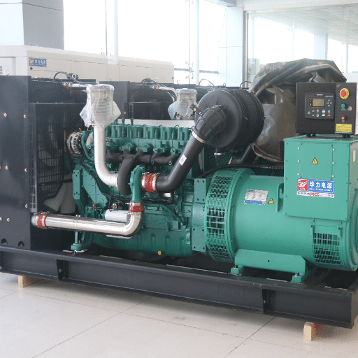



A proper generator set electrical connection requires correctly sized conductors, a matched automatic transfer switch, and grounding and bonding that complies with NEC Article 250. Get any of these three elements wrong, and the system will fail when you need it most.
In 2024, a hospital project in Singapore completed the installation of a 1,500 kW generator set on schedule. The electrical contractor sized cables using standard load calculations. Everything tested fine at no load. During the first simulated outage, the generator started perfectly, but the transfer switch refused to close. The cause was a neutral-ground bonding conflict. The generator had been shipped with a factory bond, and the contractor added a second bond at the transfer switch. The resulting ground loop triggered the ground fault relay every time the ATS attempted to transfer. The fix required rewiring the neutral bus, replacing one component, and retesting. Total delay: 11 days.
That scenario is more common than most project teams expect. The electrical connection phase is where precision engineering meets field installation, and the gap between the two is where expensive mistakes happen. In this guide, we cover every electrical connection from the generator terminal box to the load distribution panel. You will learn conductor sizing, grounding rules, transfer switch selection, voltage drop calculations, and paralleling basics.
For full-process engineering implementation specifications of industrial generator set installation, ( see our generator set installation guide).
Key Takeaways
- NEC Article 445 requires generator conductors sized at minimum 115% of nameplate current; voltage drop should not exceed 3% on feeders
- There must be one and only one neutral-to-ground bond in the entire system; the choice between 3-pole and 4-pole ATS determines where that bond lives
- ATS continuous rating must equal or exceed 115% of generator full-load amps and match the main breaker size
- Generator sets with reconnectible alternators (12-lead) allow voltage reconfiguration (380V/415V/480V) at the terminal box
- Paralleled generators require synchronization controls, reverse power protection, and ground fault coordination downstream of the parallel bus
Generator Set Electrical System Overview

Before making any connections, understand the complete power path. Electricity flows from the generator alternator, through the main circuit breaker, to the automatic transfer switch, and finally to the load distribution system. The utility supply connects to the same transfer switch on a separate set of terminals.
Key Electrical Components
The generator alternator produces AC power at the terminals inside the customer connection box. A main circuit breaker protects the generator output from overload and short-circuit conditions. The automatic transfer switch selects between utility and emergency sources. The distribution panel delivers power to individual loads.
Control wiring runs parallel to the power path but must remain physically separated. Generator controllers monitor voltage, frequency, and current. They communicate with the ATS to initiate transfer when utility power fails.
Voltage and Frequency Standards
Industrial generator sets commonly produce 380V, 415V, or 480V at 50Hz or 60Hz. Three-phase output uses four wires: L1, L2, L3, and neutral. Single-phase sets use L1, L2, and neutral. Always verify that the generator voltage matches the facility requirement before making any connections.
For a structured commissioning workflow aligned with NFPA 110 and manufacturer warranty requirements, including a digital checklist framework, see our dedicated guide on the generator set commissioning procedure.
Generator Terminal Connections: What the Factory Provides
Factory-supplied generator sets include a customer connection box with clearly marked terminals. Understanding what the factory provides prevents field wiring errors.
Standard Terminal Box Configuration
Most industrial generator sets use a terminal box mounted on the alternator frame. Power terminals accept copper lugs sized for the rated current. A separate ground stud connects to the generator frame. A control terminal block provides connections for remote start, monitoring, and alarm signals.
The factory ships generators with all terminals labeled. Never assume terminal positions are universal. Always verify against the wiring diagram provided with the unit.
12-Lead Reconnectible Alternators
Many industrial alternators feature 12 reconnectible leads. This allows voltage reconfiguration without replacing the alternator. For example, a generator set can be rewired from 380V to 415V or 480V by repositioning jumpers in the terminal box. This is particularly valuable for export projects where the destination voltage differs from the factory test voltage.
Reconnection requires following the manufacturer’s diagram exactly. Incorrect lead connections produce unbalanced voltage, overheating, and potential winding damage.
Factory-Shipped Neutral-Ground Bond
Generator sets often ship with the neutral bonded to ground inside the alternator terminal box. Whether this bond remains depends on the transfer switch type. For separately derived systems with a 4-pole ATS, the factory bond stays. For non-separately derived systems with a 3-pole ATS, the factory bond must be removed. Only one neutral-to-ground bond may exist in the entire system.
Conductor Sizing for Generator Feeders
Cable sizing is the most common electrical connection error. Undersized conductors overheat. Oversized conductors waste money. The correct size balances ampacity, voltage drop, and fault current requirements.
NEC Article 445 Conductor Sizing
NEC Article 445.13 requires conductors between the generator and the first disconnect to have an ampacity not less than 115% of the generator nameplate current rating. This applies to both phase conductors and the neutral. For a 1,000 kW generator at 480V three-phase, the full-load current is approximately 1,202 amps. The minimum conductor ampacity is 1,382 amps.
Temperature correction factors apply when ambient temperatures exceed 30 degrees C or when multiple current-carrying conductors share a conduit. Always apply the appropriate correction factor from NEC Table 310.16.
Voltage Drop Calculation
Voltage drop is not explicitly mandated by the NEC, but Article 215 recommends a maximum of 3% on feeders and 5% total. For generator applications, voltage drop matters more than for utility-fed circuits because motor starting current can be five to eight times the running current.
The accurate method uses NEC Chapter 9, Table 9, which accounts for AC impedance including resistance and reactance. For a three-phase circuit:
Voltage Drop = 1.732 x I x (R cos θ + X sin θ) x L / 1000
Where I is line current, R and X are impedance values from Table 9, θ is the power factor angle, and L is one-way circuit length in feet.
A contractor in Mexico installed a 500 kW generator 300 feet from the main distribution panel. Using the NEC approximation, cable sizing appeared adequate for running load. During commissioning, a 100 HP fire pump motor failed to start. The inrush current caused voltage drop to 72% of nominal. The contractor had to upsize phase conductors from 2/0 AWG to 4/0 AWG and install a separate conduit. Rewiring cost $8,500 and delayed project handover by two weeks.
Equipment Grounding Conductor Sizing
NEC Table 250.122 sizes the equipment grounding conductor based on the rating of the overcurrent device. When phase conductors are upsized for voltage drop, NEC 250.122(B) requires the EGC to be increased proportionally based on the circular mil ratio of the upsized conductor to the standard conductor.
Cable Sizing Quick Reference
| Generator kW | 480V 3-Phase Amps | Copper Cable Size | Conduit Size |
|---|---|---|---|
| 50 kW | 75 A | 3 AWG | 1.5 inch |
| 100 kW | 150 A | 1/0 AWG | 2 inch |
| 250 kW | 376 A | 600 kcmil | 3.5 inch |
| 500 kW | 752 A | 2 x 350 kcmil | 4 inch |
| 1000 kW | 1,202 A | 3 x 400 kcmil | 5 inch |
| 2000 kW | 2,405 A | 5 x 500 kcmil | 6 inch |
For a deeper engineering analysis of concrete specifications, vibration isolation products, and load calculations by kW class, refer to our dedicated guide on generator set foundation design.
Grounding and Bonding: NEC Article 250

Grounding and bonding errors cause more generator electrical failures than any other single issue. The rules are specific, and the consequences of getting them wrong range from nuisance tripping to lethal shock hazards.
The Single Most Important Rule
There must be exactly one neutral-to-ground connection in the entire system. A second bond creates parallel current paths on the ground conductor. This causes objectionable current flow, inaccurate ground fault protection, and shock hazards at any grounded surface.
Separately Derived Systems
When the transfer switch switches the neutral conductor (4-pole ATS), the generator becomes a separately derived system per NEC 250.30. In this configuration, the neutral must be bonded to ground at the generator. A grounding electrode conductor connects the generator to a grounding electrode. The bond at the main service entrance must be removed or isolated.
This configuration is required when the generator supplies multiple buildings, when the utility neutral is not available at the generator location, or when ground fault protection coordination demands it.
Non-Separately Derived Systems
When the transfer switch does not switch the neutral (3-pole ATS), the generator is not a separately derived system. The generator neutral must remain isolated from ground. The single neutral-to-ground bond remains at the main service entrance only. The generator frame connects to the equipment grounding conductor, but the neutral bus floats.
This is the most common configuration for single-building installations. It is simpler, less expensive, and avoids the need for a separate generator grounding electrode.
Grounding Electrode Conductor Sizing
NEC Table 250.66 sizes the grounding electrode conductor based on the largest ungrounded service-entrance conductor. For copper conductors, sizes range from 8 AWG for small generators up to 3/0 AWG for very large installations.
Ground resistance should measure 5 ohms or less. If higher resistance is measured, add ground rods or use ground enhancement material.
Unsure about your grounding configuration? See our guide to common generator set installation mistakes for real-world grounding errors and how to avoid them.
Automatic Transfer Switch Selection and Connection
The automatic transfer switch is the decision point in the electrical system. It monitors utility power, commands the generator to start when utility fails, and transfers the load to the generator. ATS selection affects safety, reliability, and code compliance.
ATS Sizing Rules
The ATS continuous current rating must equal or exceed the main breaker rating. It must also equal or exceed 115% of the generator full-load current. The short-circuit withstand rating must match or exceed the available fault current from either the normal source or the emergency source, whichever is greater.
For example, a facility with a 1,600-amp main breaker and a 1,250-amp generator requires a minimum 1,600-amp ATS. The next standard size is typically selected.
3-Pole vs 4-Pole ATS
The choice between 3-pole and 4-pole transfer switches determines the grounding system configuration. Use 3-pole (solid neutral) for single-building installations where the generator neutral is not grounded at the set. Use 4-pole (switched neutral) when the generator is a separately derived system, when supplying multiple buildings, or when ground fault protection coordination requires switched neutrals.
Choosing the wrong pole configuration creates either a missing neutral-ground bond or a double bond. Both conditions cause protection system failures.
Open Transition vs Closed Transition
Open transition switches break the load connection to the utility before connecting to the generator. There is a brief interruption, typically under 250 milliseconds. This is acceptable for most loads and is the standard configuration.
Closed transition switches momentarily parallel the utility and generator sources before transferring. This provides uninterrupted power but requires synchronization, permissive utility interconnection agreements, and combined fault current analysis.
ATS Wiring Connections
Power wiring connects the normal source (utility), emergency source (generator), and load to the appropriate ATS terminals. Control wiring provides utility monitoring, generator start signals, and status indication. Control conductors must be run in separate conduits from power conductors to prevent electromagnetic interference.
Paralleling Generator Sets: Electrical Connections
When a single generator cannot provide sufficient capacity or redundancy, multiple units operate in parallel. Paralleling adds complexity to every electrical connection in the system.
Synchronization Requirements
Before closing a generator breaker onto a live bus, the generator voltage, frequency, and phase sequence must match the bus. Synchronizing devices measure these parameters and issue a close command when conditions are within tolerance. Closing out of phase produces current surges that can damage generator windings and breakers.
Parallel Bus and Switchgear
Each generator connects through its own circuit breaker to a common parallel bus. The bus feeds the transfer switch or load distribution system. Each generator breaker requires reverse power protection to prevent a failed unit from becoming a motor and drawing power from the bus.
Ground Fault Protection Coordination
In paralleled systems, a common misconception is placing ground fault protection on every generator breaker. This is incorrect. A single ground fault would then disable the entire emergency system. Ground fault protection belongs on the feeder downstream of the parallel bus, protecting the distribution system while keeping all generators online.
Load Sharing Controls
Paralleled generators share load using either isochronous or droop control. Isochronous control maintains exact frequency and shares load proportionally. Droop control allows frequency to decrease slightly with increasing load. The control system wiring between generator controllers is as critical as the power wiring.
In 2023, a data center in Brazil installed two 2,000 kW generators with plans to parallel them for N+1 redundancy. The installation contractor wired the synchronizing check relay to the wrong set of potential transformers. During the first paralleling attempt, the generators were 30 degrees out of phase when the breaker closed. The resulting mechanical and electrical shock damaged both generator windings and shattered one breaker mechanism. Repairs cost $45,000, and the data center operated on a single generator for six weeks.
Voltage Drop Calculation: Step-by-Step

Voltage drop calculations determine whether conductor sizing is adequate for the actual installation conditions. The NEC Chapter 9, Table 9 method provides accurate results for AC circuits.
NEC Table 9 Method
For a three-phase circuit, the formula is:
VD = 1.732 x I x (R cos θ + X sin θ) x L / 1000
For a 500 kW generator at 480V, 500 feet from the load, using three 500 kcmil copper conductors in steel conduit, with 0.85 power factor:
I = 752 A
R = 0.029 ohms per 1,000 ft (from Table 9)
X = 0.048 ohms per 1,000 ft (from Table 9)
cos θ = 0.85, sin θ = 0.527
VD = 1.732 x 752 x (0.029 x 0.85 + 0.048 x 0.527) x 500 / 1000
VD = 1.732 x 752 x (0.0247 + 0.0253) x 0.5
VD = 1.732 x 752 x 0.050 x 0.5
VD = 32.6 volts
Percentage VD = 32.6 / 480 x 100 = 6.8%
This exceeds the recommended 3% and would likely cause motor starting problems. The solution is either to upsize conductors or move the generator closer to the load.
When Voltage Drop Governs Cable Size
Voltage drop typically governs conductor sizing for runs exceeding 100 feet, for low-voltage systems (208V or 380V), and for circuits feeding large motors. In these cases, the conductor required for voltage drop will be larger than the conductor required for ampacity alone.
Common Electrical Connection Mistakes to Avoid
Even experienced contractors make electrical connection errors. Recognizing these common mistakes before installation saves time, money, and potential safety hazards.
Undersized conductors top the list. Contractors often size cables for running load without applying the 115% NEC multiplier or checking voltage drop under starting conditions.
Wrong neutral-ground bonding causes protection system failures. The most common error is leaving the factory bond in place while using a 3-pole ATS, creating a double bond.
3-pole vs 4-pole ATS confusion leads to both grounding errors and loss of ground fault protection coordination. Always verify the system grounding configuration before ordering the transfer switch.
Missing voltage drop calculation produces motor starting failures. Always calculate voltage drop at both running and starting current.
Inadequate short-circuit withstand ratings create catastrophic failures during fault conditions. The ATS and all connected switchgear must withstand the maximum available fault current from either source.
Control wires in power conduits cause EMI problems that trigger false alarms and erratic transfer switch behavior. Always separate control and power wiring.
For deeper coverage of day tank configurations, piping material selection, and leak detection codes, see our guide on generator set fuel system installation.
2026 NEC Changes Affecting Generator Electrical Connections
The 2026 National Electrical Code introduces several changes that affect generator set electrical installations. Project teams designing systems for 2026 and beyond should account for these updates.
Stricter grounding electrode system requirements may require additional ground rods or enhanced grounding grids for separately derived systems. The 2026 code emphasizes lower ground resistance values.
New conductor derating factors apply in certain installation conditions. Review Article 310 adjustments for ambient temperature and conduit fill.
Enhanced surge protection requirements mandate surge protective devices at generator outputs, transfer switches, and critical load panels. This responds to the increasing frequency of lightning-induced damage to electronic controls.
Energy storage integration requirements address hybrid systems combining generators with battery storage. New disconnecting means and control interlocks apply when batteries share the electrical system with engine-generators.
Conclusion
The five critical elements of a generator set electrical connection are conductor sizing, grounding and bonding, transfer switch selection, voltage drop verification, and paralleling controls when multiple units are involved. Each element has specific code requirements, and each interacts with the others.
A properly executed electrical connection ensures that when utility power fails, the generator starts automatically, the transfer switch closes without hesitation, and the load receives stable power within acceptable voltage and frequency limits. A poorly executed connection creates the exact opposite: failure precisely when reliability matters most.
Electrical connection work should always be performed by licensed electricians familiar with NEC Article 445 and Article 250. For complex installations involving paralleling, closed-transition transfer, or custom voltage configurations, engineering review before installation prevents costly rework.
Need electrical connection drawings for your project? Our engineering team provides terminal connection diagrams, single-line drawings, and cable sizing calculations for generator sets from 5 kW to 3,000 kW. Contact us for project-specific electrical support.