
Generator transient response testing needs an agreed load event, distinct voltage and frequency limits, and a clear recovery rule. Set these out before testing, together with the measurement point and the records needed to judge the result.
A stable reading at the end cannot show the deepest dip or how long recovery took. Buyers and suppliers can agree on rated power yet expect different behavior during the first load change. This guide turns those expectations into fields that both parties can review before a witness test.
Key takeaways
- Define the starting load, added or removed demand, and load behavior for each event.
- State voltage and frequency limits separately, including their reference values.
- Define recovery by its band, timing start and sustained-return rule.
- Link each acceptance decision to a trace, configuration and approved test revision.
Before inviting witnesses, add these fields to your generator inspection and test plan. Leave an unresolved criterion open for approval; do not turn an empty cell into a pass.
Define what generator transient response testing must prove
Choose the equipment boundary
Start with the question the test must answer. Are you checking the set at its terminals, or the site power system at a load connection? A set on a load bank and a site feeding motors through switchgear have different test boundaries. Draw the boundary first.
List what is inside it: the set, cables, switches and connected loads, as needed. Mark where you will measure on the drawing. A reading at the set terminals does not prove what a distant motor or control panel sees. Keep the point and its label the same on every test sheet.
Use the wider generator set commissioning procedure for installation and system checks. Keep this agreement focused on the load changes and response being assessed. List transfer, protection and load checks in their own scope. Don’t assume that one transient run covers them all, or that a witness will infer the intended scope from a drawing alone.
Name the standard, edition and approver
A performance-class label needs a defined test basis. Caterpillar’s transient specification paper explains the problem with treating a custom load step as equivalent to the steps behind a named class. Ask the supplier to identify the applicable schedule and separately confirm your application events.
The ISO catalogue lists ISO 8528-5:2025, published in May 2025. Older technical papers may discuss earlier editions. Name the edition the project adopts; do not copy a historical performance table without checking that it applies. The catalogue establishes edition information, not the limits for your contract.
Illustrative scenario: A buyer writes “G3” and expects the first event to connect every critical load. The supplier expects a defined staged schedule. Neither expectation is a complete event sheet. The useful next step is to agree the schedule and criteria before test release, instead of arguing over a label after the run.
Name the person who can approve the test limits, the test operator and the witness. Keep document revision and approval status visible. Mark which sheets are proposals and which are approved for use.
Agree the starting load, added step and rejection event
Describe before, change and after
“Apply 50% load” leaves key questions open. Does it mean start at no load and reach half rating, or add half rating to an existing load? Which rating is the percentage based on? Does the demand arrive as a block or a ramp?
Put real load values beside each percent. Active power in kW shows real power demand; apparent power in kVA and reactive power in kVAr help define the load. Power factor relates active to apparent power. State the rating basis, voltage and frequency so readers know what the numbers refer to.
Illustrative scenario: On a hypothetical 1,000 kW rating basis, adding 300 kW to a 200 kW pre-load gives a 500 kW final load. Going from zero to 500 kW reaches the same final value but adds 500 kW. This is arithmetic only, not a test result or a recommended loading schedule.
Use a blank event matrix like this, with one row for each approved event:
| Agreement field | Value to enter before testing |
|---|---|
| Event ID and direction | Named addition or rejection event |
| Starting condition | Initial kW and kVAr, or kVA and power factor |
| Change | Added or removed demand and its rating basis |
| Final condition | Expected demand after the change |
| Load behavior | Bank, motor, UPS or other defined load |
| Event shape | Block, ramp or staged sequence with timing |
| Readiness condition | Warm-up, stability and reset requirements |
| Approval reference | Schedule revision and approving party |
Do not leave rejection implicit. Identify which load is removed, what remains connected, and the rise and recovery limits. Include the next allowed event only after the agreed readiness condition is met. That makes the sequence clear to repeat rather than dependent on an operator’s guess.
Match the load behavior
A resistive load bank does not represent every motor or electronic load. Motor starting adds a distinct demand event; its starting method and the loads already running matter. Refer detailed starting issues to the guide on motor-start voltage drop.
UPS input controls can also change how demand builds. Caterpillar’s constant-power load paper distinguishes load behaviors and examines ramping. Its simulation examples should not become a universal ramp setting. Ask how the actual load draws power, and confirm walk-in settings and current limits where relevant.
For a standard-based schedule, request the manufacturer’s schedule for the specified set and adopted edition. Engine loading stages may involve brake mean effective pressure, or BMEP, rather than a convenient equal-percentage sequence. For a custom event, agree both the event and its limits in writing. The same final kW does not prove that two tests place the same demand on the set.
Set voltage, frequency and recovery criteria separately
Fix the reference and extrema
Record voltage and frequency as separate channels. A frequency reading near its rated value does not prove that voltage stayed in range. Capture both through the whole event.
The Cummins transient-performance paper explains dip, rise and recovery bands. Check which standard edition your project uses before you copy any of its older limits.
For voltage, state whether the reading is line-to-line or line-to-neutral. Name the phases to check. For each channel, state the reference value used to judge the change.
Is it the rated value, the nominal value or the value just before the step? Use the basis required by the agreed method. Don’t let the reader guess what a percent means.
If the sheet uses “dip percentage,” show the math beside it. For an agreed reference X, one way to define dip size is 100 × (X − minimum) / X. A rise could use 100 × (maximum − X) / X. These are worksheet rules for the parties to approve.
They are not a claim that all standards use this basis or sign rule.
Keep the lowest and highest readings as well as the percent change. That lets the reviewer check the math and find which phase or channel set the result. State whether the limit applies to each phase or some other agreed value. Don’t judge an average against a rule meant for each phase.
Define recovery before measuring time
Ask three things: what came back into range, which range, and when did the clock start? Set the lower and upper recovery bounds for voltage and frequency. They need their own rows. Define the start marker, such as the recorded load-switch event, and show how to find it in the data.
Then define the timer’s end. The first entry into a band may not be a sustained return. Agree what happens if the trace leaves the band again. State how long to observe it or which rule proves stable return.
Use that same rule on the test sheet and the plot. A reviewer should get the same time from the same trace.
Place the criteria matrix beside the load-event schedule:
| Channel | Reference and unit | Extreme limit | Recovery band | Time rule | Approved by |
|---|---|---|---|---|---|
| Voltage, named phases | Enter reference | Enter dip/rise limits | Enter lower/upper bounds | Start, return rule, deadline | Name/revision |
| Frequency | Enter reference | Enter dip/rise limits | Enter lower/upper bounds | Start, return rule, deadline | Name/revision |
| Load behavior | Name the equipment | Enter allowed behavior | If needed | Rule for what to observe | Name/revision |
The project approver must supply the values. A generic table cannot settle an open question about the load, set or test point. Keep those fields open until the right person signs them off.
For a schematic trace, mark the value before the step, the step start, the peak or low point, the band and the accepted return point. Label it as a schematic, not real test data. Show a brief band entry followed by an exit if that helps explain the rule. Keep peak limits, recovery times and steady limits distinct; meeting one does not prove the others.
Capture evidence that can resolve a transient test result
Record the configuration and conditions
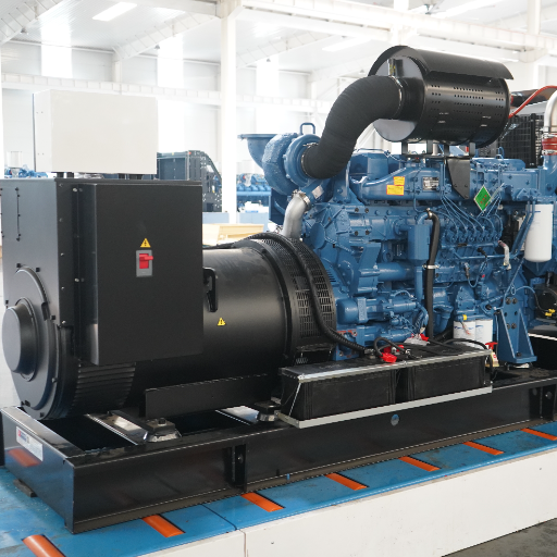
Tie the event sheet to the exact set being tested. Record the set, engine, alternator and controller IDs available for the run. Add relevant control settings and software references.
The governor controls engine speed; the automatic voltage regulator, or AVR, controls excitation. This guide does not prescribe how to tune them.
Note the site and running conditions that the test procedure calls for. Include warm-up status, whether readings were stable at the start, fuel grade where relevant, and the load equipment in use. Keep the same fields so reviewers can tell what changed between runs.
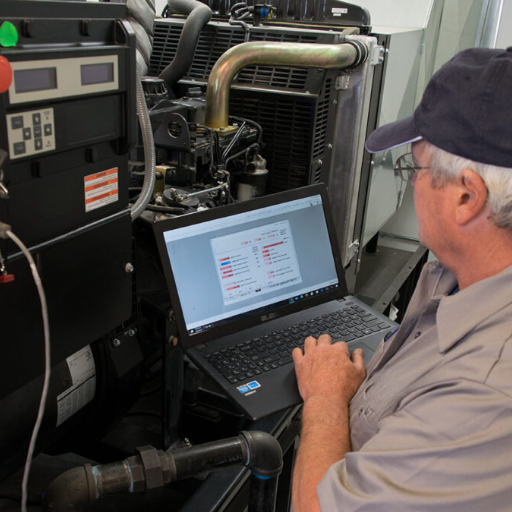
Agree the recorder and the whole chain used to take readings before the witness arrives. List the instruments, calibration references, probes or transducers, ranges and test points. Ask the test engineer to show that the chosen capture settings can resolve the event and support the pass/fail decision. This worksheet does not supply one sample rate for all tests.
Make the event visible in the data
Capture the agreed voltage and frequency channels, current or load measurements, and the event timing needed to interpret the response. Record the trigger, time base, capture length, data settings and any filters that affect the plot. Keep raw waveforms distinct from derived trends; the test engineer should explain which outputs support each test limit.
Use an event ID to connect the schedule, trace and summary. Agree a file index with the test engineer:
| Index field | What a reviewer needs to find |
|---|---|
| Event ID and time | The matching row in the approved schedule |
| Setup revision | The set and settings used for this run |
| Recorder file | The original data for this exact event |
| Report figure | The plot with units, channels and time axis |
Keep data from before and after the event. Show the starting state and the whole agreed recovery interval, not just the dip.
For trace annotation, use this order: identify the event marker, show the reference and boundaries, mark the extreme, then mark the point of return under the agreed rule. Keep voltage and frequency on a shared time reference where the capture method allows it. A plot should let another reviewer check the reported values, not just see a smooth curve.
Request the records with the report
Ask for the trace files, readable plots, instrument settings and a signed event-to-result table as part of the generator load test report. Agree file types and review access before the test. Retain the original capture alongside any annotated copy.
A controller screenshot or video can provide context, but it may omit the deepest excursion, timing detail or capture settings. Use it as supporting material only unless its method meets the agreed test needs. A final panel reading cannot show a transient that was not captured.
Decide acceptance, exceptions and retests against the agreed scope

Judge each event against its approved row
Build the decision table around the same event IDs. For each event, enter the actual starting load, actual change, observed extrema, recovery times, agreed limits and trace references. Record alarms, trips and what the included load equipment did. Record out-of-scope findings on their own; do not merge them into the test result.
Give each event a clear decision:
| Decision | Basis to record |
|---|---|
| Accepted | Trace meets the approved limits for this event |
| Not accepted | Named limit was not met; cite the trace |
| Not assessed | A required limit or record is missing |
A blank time field does not mean recovery took zero seconds. You can’t pass an event that was never captured.
For an exception, record the requirement, observation, evidence reference, responsible person and decision due. The person in charge should say whether more data, a change or a repeat is needed. If the result has a condition, keep that exact condition and the proof that closes it. Avoid a broad “all satisfactory” statement that conceals open events.
Preserve changes and repeat scope
Illustrative scenario: A control setting changes before a repeat run. The new trace may answer whether that configuration meets the criteria, but it does not erase the first record. Record the setting change and ask which earlier events must be repeated. Do not assume either a successful correction or a fault diagnosis from the change alone.
Use a retest record with five fields: original event and trace; reason for repeat; approved change; repeat scope and conditions; new result and decision. Preserve both records and connect them with a revision reference. If the load sequence also changes, make that difference explicit instead of treating the runs as the same.
Close acceptance at the defined boundary. Factory set testing does not by itself accept site cables, transfer logic or installed equipment behavior. Carry those items into their agreed site checks. This keeps the transient decision useful without expanding it into a claim that the whole installation has been proven.
Questions buyers ask before a transient response test
Is a G3 label enough to specify the test?
No: identify the adopted standard edition, relevant loading schedule, equipment configuration and agreed limits. Then state any custom application events separately. A class label does not describe every possible starting load or block step. Ask the supplier to show how the proposed test matches the requirement you intend to assess.
Must every generator accept zero to full load in one step?
Do not assume that requirement. Establish the applicable standard-based schedule and the actual site demand sequence with the manufacturer. If your project needs a particular single-step event, specify its starting condition, electrical demand, load behavior and acceptance limits. Obtain agreement for the selected configuration instead of relying on a generic percent.
Can a resistive load bank prove the response to a UPS?
A resistive bank can serve the test defined for that bank. It does not by itself mimic how a UPS draws power. State power factor, demand changes, walk-in settings and current limits where relevant. Agree what the chosen test represents and what needs a separate equipment or installed-system check before drawing a wider conclusion.
When is recovery complete?
Recovery is complete when the recorded channel meets the approved return rule. That requires a defined band, timing start and treatment of later departures from the band. Voltage and frequency may have different criteria. Do not substitute the first visible crossing or a final steady reading for the rule agreed before testing.
Can a screenshot or video prove the result?
Only if the evidence contains the measurements and timing required by the approved method. A typical panel image or process clip may lack extrema, recovery detail and recorder settings. Request trace files with channel labels, units and event identity. Treat visual context separately from the measured data used to judge the test.
Does a factory acceptance test accept site behavior too?
Only the stated test boundary is assessed. A factory test on the set does not by itself prove behavior through site cabling, switching equipment and installed loads. Identify what was included, what was simulated and which site checks remain. Carry the same event definitions forward where comparison is intended, and document relevant differences.
Take an agreed transient test schedule to the supplier
Take these documents to the supplier for written review:
- A load list and the proposed set and control setup.
- An event sheet with starting demand, each change and final demand.
- Separate voltage and frequency limits, with bands and timing rules.
- A marked test boundary and the list of trace files to supply.
Use the same event IDs in each document. Ask the supplier to confirm the schedule in writing and flag open points. Name the project approver. Close the open fields before you commit the test equipment and invite witnesses.
Use the ITP to control the agreement and the report to record what happened. Link changes and retests to the first run. Both parties should be able to answer three questions from these documents: what was required, what was measured, and why the result was accepted or left open. A stable final reading is only one part of that evidence.