
Generator neutral earthing is a choice between five methods, and the method decides the earth fault current the alternator will ever see. At medium voltage the answer is rarely solid earthing. It’s usually a resistor, sized to a current the winding and the protection relay can both live with.
Most specifications do the opposite. They name a voltage, a kVA and a frequency, then leave earthing to the supplier, as though it were a paint colour. It isn’t. The method changes what the machine can survive and what the relay can detect.
This article covers the five methods and what each one costs, why a generator isn’t earthed like a transformer, the arithmetic behind the resistor value, and what changes when sets run in parallel. It stays above 1 kV throughout. If you’re working on a low-voltage set, the low-voltage grounding and bonding rules are a different problem with a different answer.
If you already have a data sheet, send us the earthing line and we’ll check whether the resistor value and the relay setting agree.
Key Takeaways
- An 11 kV neutral earthing resistor is plated at 6.35 kV, because it only ever sees line-to-neutral voltage.
- The value comes from R = (11/√3) / I. At 10 A that’s 635 Ω, and the standard short-time rating is 10 seconds.
- Solid earthing isn’t the default above 1 kV. A solidly earthed generator can see an earth fault current higher than its three-phase fault current, and the machine is only built to withstand the three-phase level unless the specification says otherwise.
- On an isolated system with several generators in parallel, only one neutral is normally earthed at a time.
- Protection is usually set at 20 to 50% of the resistor current, so the resistor value and the relay setting are one decision, not two.
What the Neutral Does on a Medium-Voltage Generator
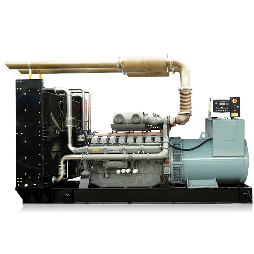
The neutral point is earthed for two reasons, and neither of them is operator safety. The first is to protect the stator winding. The second is to stop transient overvoltages when an earth fault arcs or the system ferroresonates.
Everything else in this article follows from those two jobs. An earthing method that protects the winding well may leave the protection relay blind. A method that lets the relay see everything may let the fault burn the core before the breaker opens.
The neutral is also a design output, not an accessory. Some alternators bring it out to the terminal box. Some don’t. On the 11 kV data sheet, the neutral arrangement belongs in the second block, beside the CT ratios and the reactances.
It’s an input to the protection study, not a line on the order.
The word splits by standard rather than by engineering. What IEC practice calls generator neutral earthing, North American practice calls generator neutral grounding. The method and the arithmetic are identical either way.
At low voltage this is usually simpler. LV generators are normally solidly earthed, with marine applications as the standing exception. Above 1 kV that shortcut closes, and the reason is in the next section.
The Methods, and What Each One Buys
Five methods cover almost every medium-voltage generator, and the column that matters is the current each one leaves for the protection to detect.
| Method | Typical earth fault current | Where it fits | What it costs you |
|---|---|---|---|
| Solid | Can exceed the three-phase fault current | Only where the machine was designed for it | Large fault current, core damage |
| Low resistance | 200 A to 400 A | Large machines with their own protection | Resistor cost and upkeep |
| High resistance | 10 A to 20 A, often 10 A or less up to 15 kV | Smaller sets, alarm rather than trip | Weak detection near the star point |
| Reactance | Set by the reactor | Current limiting without resistor heat | Harder to size, less common |
| Isolated | Charging current only | Short cable runs, special cases | Transient overvoltages, needs supervision |
Those current figures aren’t arbitrary. The 200 A to 400 A band and the 10 A to 20 A band are the common values for high-voltage generators. High-resistance schemes sit at the low end, typically 10 A or less for generators up to 15 kV.
The trade is the same in every row. A lower fault current does less damage and is harder to detect. A higher one is easier to protect and does more damage while the protection decides.
There’s a floor under solid earthing that surprises people. The guidance is blunt: the neutral of a generator should not be solidly grounded unless the generator was specifically designed for that operation. Most weren’t.
If you’re still deciding whether the site needs medium voltage at all, the medium-voltage versus low-voltage comparison comes first. Earthing only matters once the voltage class is settled.
Why a Generator Is Not a Transformer
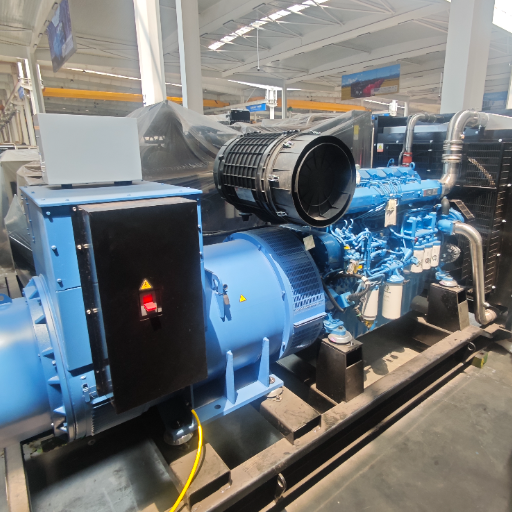
The reflex is to copy the transformer’s earthing arrangement. It doesn’t transfer, for two reasons.
The fault current can exceed the machine’s fault rating. A solidly earthed generator will usually have a higher initial earth fault current than its three-phase fault current. An IEEE guide on generator grounding puts it this way: the machine is required to withstand only the three-phase level unless the specification says otherwise. In other words, the fault the earthing creates can be larger than the fault the machine was built to ride through.
The third harmonic has somewhere to go. A loaded generator develops a significant third-harmonic voltage. With a solidly earthed neutral and no external impedance, that current can approach rated current. A resistor or a reactor gives it somewhere else to dissipate.
Hanna Brandt ran into the second one at a combined heat and power plant outside Leipzig. The 6.6 kV set had been solidly earthed on the grounds that the plant’s transformer was, and the two should match. The set tripped on earth fault several times a week for a month, always under load and never with a fault anyone could find.
The cause was third-harmonic current in the neutral, which doesn’t show up as a fault at all. Fitting a resistor removed the trips and gave the relay a current it could discriminate. The plant had spent four weeks replacing a protection scheme that was working correctly.
Hanna’s case is the common one. However, the transformer comparison feels like engineering and is actually pattern matching. A transformer’s earthing is chosen for the network it feeds. A generator’s earthing is chosen for the machine it protects, and the machine has a laminated core that doesn’t survive a sustained internal fault.
Sizing the Neutral Earthing Resistor
Four numbers go on the specification: voltage, current, time and temperature. Get the first one wrong and the other three don’t matter.
The Plate Says Line-to-Neutral
An “11 kV NER” is rated 6.35 kV on its rating plate, because 6.35 kV is 11 divided by √3. The resistor never sees the full line-to-line voltage, even during a phase-to-earth fault.
Specifiers still ask for insulation rated to the system voltage. That makes the resistor larger, heavier and more expensive for no electrical benefit, and on a packaged set it can cost you the enclosure.
Faisal Al-Mutairi found that out on a desalination plant in Ras Al Khair. The package arrived with a resistor insulated to 11 kV instead of 6.35 kV, which added enough height that the enclosure no longer cleared the cable tray above it. The electrical design was fine. The installation wasn’t, and the set sat in its crate for six weeks waiting on a replacement.
The Current, and the Arithmetic
The value follows from the current you want:
R = (system voltage / √3) / fault current.
At 11 kV and 10 A, that gives (11 / 1.732) / 10, which is 635 Ω. Aktif’s NGR catalog works the same example.
A 200 A scheme on the same system works out near 32 Ω. The arithmetic is trivial. Choosing the current isn’t.
Start with the alternator. Ask the supplier for the maximum earth fault current the machine is rated to see, and treat that figure as the cap on everything else.
Then check the other end. Protection has to operate at the current you choose, which is why a site with old relays often specifies a higher current than a site with new ones. Where no machine figure is available, the 200 A to 400 A band is a common starting point.
Time, Temperature and Tolerance
A resistor is rated for a short-time duty, not a continuous one. 10 seconds is the standard, chosen so the resistor survives multiple events, an auto-reclose, or an upstream backup device operating after the primary relay fails. A 30-second rating usually means the specification was written around an old liquid resistor.
Heat is the constraint behind the time. Element temperature rise is limited to 760 °C under IEC 60076-25 (2023) or IEEE C57.32a (2020), and those ratings assume the resistor is cold when the fault starts.
Resistance also moves as the element heats. IEEE C57.32a caps that change at 67%, so the current stays high enough for the relay to operate at the end of the duty, not just the start.
Then set the relay. Protection is typically set at 20 to 50% of the specified fault current, which means a 10 A resistor gets a relay pickup somewhere between 2 A and 5 A. Change one number without the other and you’ve built a scheme that either trips on nothing or misses a real fault.
If You Use an Earthing Transformer Instead
Where the neutral isn’t brought out, or the machine is delta-connected, an earthing transformer provides the zero-sequence path. Its continuous rating usually falls between 5 and 250 kVA, and the secondary resistor passes a short-time current typically in the 5 A to 20 A range.
Two design details matter. The resistive part of the fault current should not be less than the residual capacitance current, and in practice values of three to five times that current are used.
The transformer also has to stay out of saturation, or ferroresonance follows. Its primary knee-point e.m.f. is normally set at 1.3 times the generator’s rated line voltage for exactly that reason.
Parallel Operation and the Protection Interface
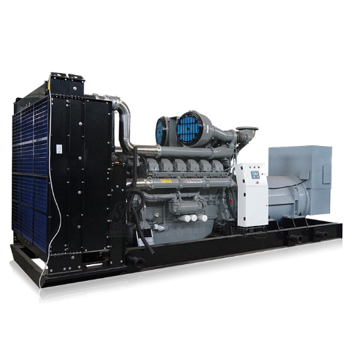
Two sets in parallel change the earthing question, because the system can now have two neutral points and only wants one earth path.
IEEE’s Green Book states the problem in its section on paralleled generators in an isolated system. Collecting neutrals and solidly earthing them together creates a path for excessive third-harmonic current. Collecting them through a single resistor can push that resistor beyond its continuous duty.
The practical rule that follows is simple to state and easy to get wrong. On an isolated system with generators connected directly at their generated voltage, only one is normally earthed at a time.
Ama Mensah inherited the opposite arrangement at a gold mine in Ghana. Three 11 kV sets ran in parallel, all three neutrals were bonded to a common earth bar, and the plant had lived with unexplained earth fault alarms for a year. Nobody had treated it as an earthing problem, because the alarms came and went with load.
Breaking two of the three neutral bonds and fitting a switched arrangement removed the alarms within a week. The remaining work was protection coordination, which was the part the plant had actually been trying to solve.
Switched neutrals are how most plants meet the rule in practice. A contactor or a breaker selects which generator’s neutral is earthed, and the selection interlocks with the paralleling scheme so the earth point moves with the running set.
The protection interface is where all of this lands. The relay needs the fault current figure, a CT on the neutral-to-earth connection, and a coordination study against the switchgear that clears the fault. Those three inputs are also what the protection setting study is built from, so the earthing design and the protection design are one document, not two.
For a packaged medium-voltage set, the generator earthing system ships with the medium voltage generator and its protection panel. Specifying it after the order is placed means fitting it in the field, which is where most of the stories in this article come from.
Frequently Asked Questions About Generator Neutral Earthing
How do you size a neutral earthing resistor?
Divide the line-to-neutral voltage by the fault current you want: R = (line voltage / √3) / current. For an 11 kV system limited to 10 A, that’s 635 Ω. Then check that the alternator’s maximum earth fault current and the relay’s pickup both sit on the right side of that figure.
Should parallel generators all have their neutrals earthed?
No. On an isolated system with sets connected directly at their generated voltage, only one neutral is normally earthed at a time. Bonding all of them together creates a path for third-harmonic current and can exceed the duty rating of a shared resistor.
Is an 11 kV generator earthed like an 11 kV transformer?
No. A transformer’s earthing is chosen for the network, and a generator’s is chosen for the machine. A solidly earthed generator can see an earth fault current above its own three-phase fault current, and the stator core damage from that fault is a repair the site can’t do.
What is the maximum earth fault current a generator can take?
The alternator manufacturer sets it, and it caps the resistor design, so it belongs in the enquiry rather than in a later email. Where no figure is available, the usual choice sits in one of the two common bands: 200 A to 400 A for low-resistance schemes, 10 A to 20 A for high-resistance ones.
Generator Neutral Earthing Ends at the Resistor Value
Generator neutral earthing comes down to three decisions, and they have to agree with each other. Choose the method, which at medium voltage usually means resistance earthing rather than solid. Size the resistor from the line-to-neutral voltage and the current you want. Decide how many neutrals are earthed when the sets run in parallel.
The numbers are short. 6.35 kV on the plate for an 11 kV system. 635 Ω at 10 A. Ten seconds.
A relay set somewhere between 20 and 50% of that current. A single earth point when sets share a bus.
What makes it hard isn’t the arithmetic. It’s that earthing is usually the last line on the data sheet and the first thing to fail in service.
If you’d rather have the scheme checked before you place the order, send the data sheet to our engineering team. We’ll mark the earthing line, cross-check the resistor against the relay setting, and point out which line the supplier left blank.